
High-power electric pulse generator

a generator and high-power technology, applied in the direction of pulse technique, generating/distributing signals, instruments, etc., can solve the problems of limiting the possibility of controlling the required, not being able to obtain, and high temporal jitter that is conventionally too great to synchronise short (subnanosecond) pulses, etc., to achieve fine control of the modulation spectrum, low temporal jitter, and high reproducibility

Inactive Publication Date: 2009-10-20
CENT NAT DE LA RECHERCHE SCI +1
View PDF4 Cites 1 Cited by
  • Summary
  • Abstract
  • Description
  • Claims
  • Application Information

AI Technical Summary

Benefits of technology

The present invention aims to provide a high-voltage pulse generator that can generate a monocycle adjustable for time and spectrally. The generator uses passive semiconductor elements in linear mode as photosensitive switches, which allows for very low temporal jitter and fine control of the signal spectrum. The generator has a long service life with low energy consumption. The use of silicon diodes reduces the jitter on triggering, and a type of silicon photosensitive semiconductor reduces the consumption of optical energy.

Problems solved by technology

The drawback of these photoconductor systems working in avalanche mode is the high temporal jitter that is conventionally too great to synchronise short (subnanosecond) pulses.
This temporal jitter in the starting of the two waves greatly limits the possibilities of controlling the required bipolar signal, and therefore the spectrum of the latter.
In addition avalanche mode does not make it possible to obtain reproducible pulses because of the chaotic character involved in the phenomenon, which in addition limits the service life of the photoswitches by local destruction of the substrate (the phenomenon of filamentation in the avalanche systems).
First of all, it will be understood that the device described in the application FR 2 679 716 makes it possible to determine whether pulses are negative or positive, according to the polarisation of the high-voltage source. This leads to a distribution of the power of the spectrum of the pulse limited to the low frequencies and does not allow control and mastery of this spectrum.
In particular, in the field of biology, if a high voltage is applied to living cells, the application of a solely positive or solely negative voltage may cause a bursting of the cell by the creation of a force field within the cell.

Method used


Image

  • High-power electric pulse generator
  • High-power electric pulse generator
  • High-power electric pulse generator

Examples


Embodiment Construction

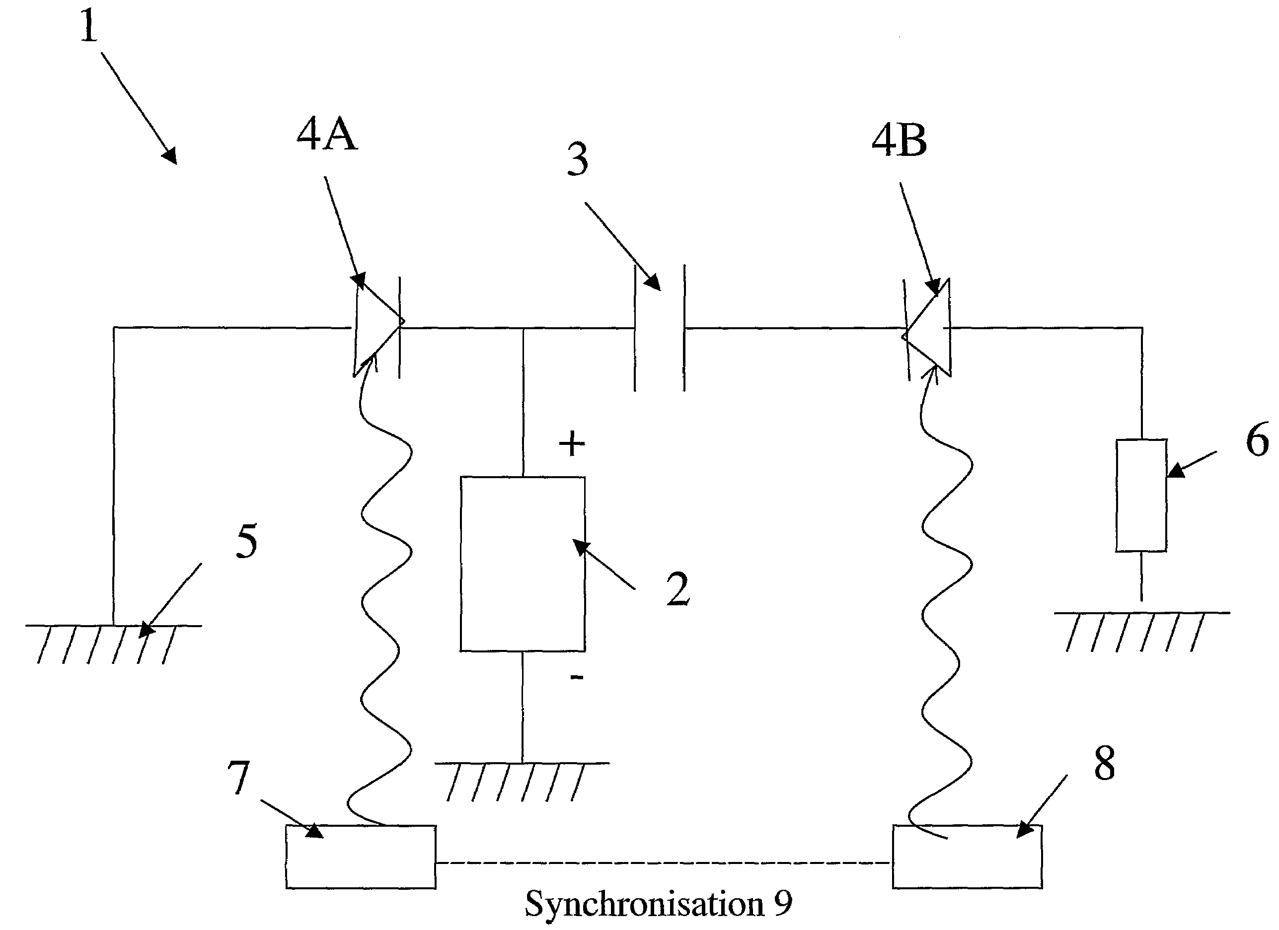
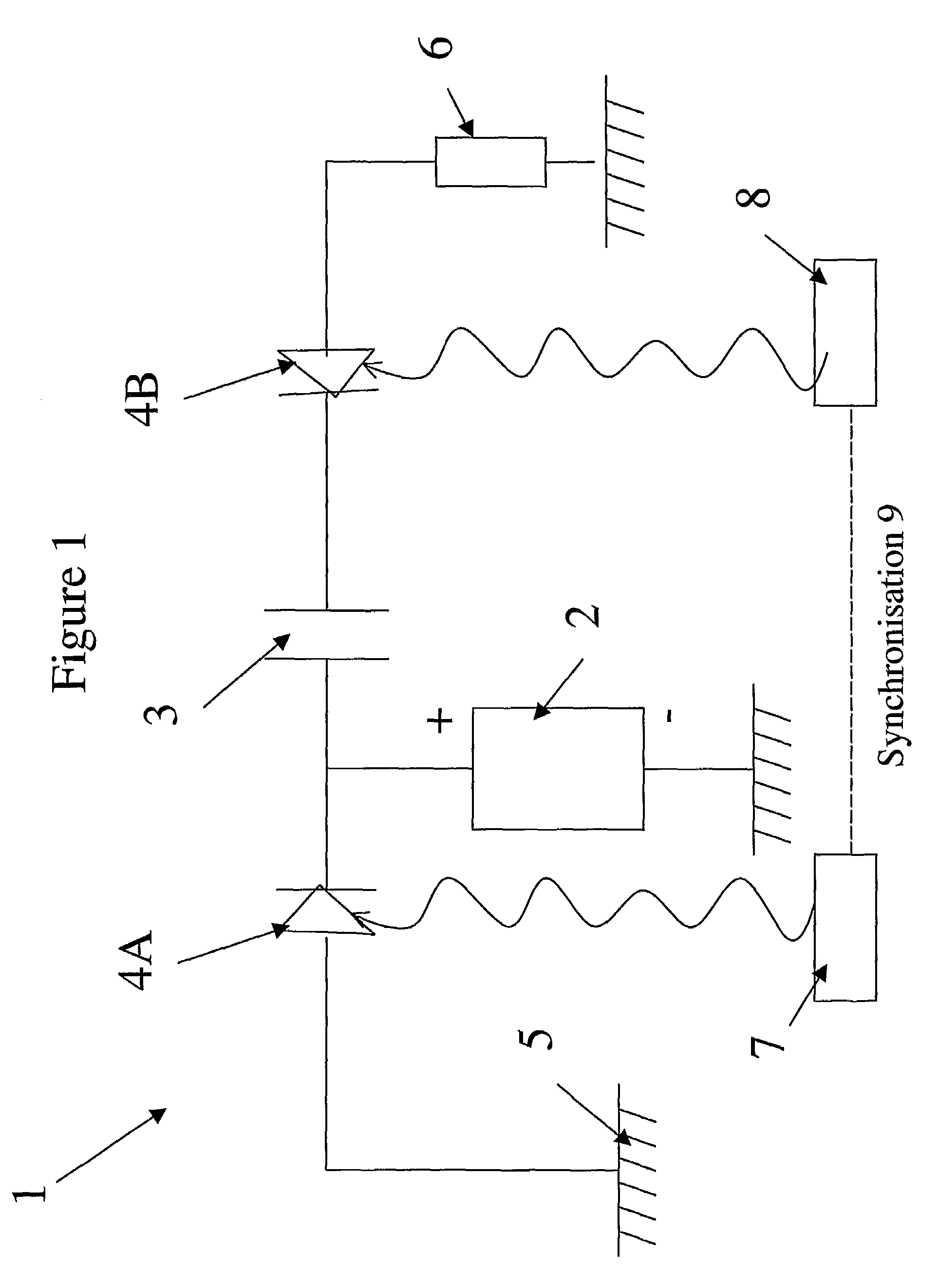
[0029]Illustrated in FIG. 1, the generator 1 comprises a high-voltage source 2 and a microwave transmission line forming a charge storage means 3. It also comprises two semiconductors 4A and 4B on each side of the transmission line 3. The first semiconductor 4A is connected to the reference of the potentials 5 and the second semiconductor is connected to a useful load 6. The semiconductors 4A and 4B are able to be excited by two light sources 7 and 8, which are coupled by a synchronisation means 9. This synchronisation means 9 makes it possible to control the delay of the laser emissions issuing from the sources 7 and 8. The sources 7 and 8 can consist of a laser source whose radiation is split into two or by two synchronous laser sources.

[0030]When the sources 7 and 8 do not illuminate the semiconductor components 4A and 4B, the latter have a high inherent resistance of several tens of Megohms, which can be considered to be open switches. After illumination by a brief optical pulse...


PUM


Abstract

A high power electric pulse generator includes a charge storage device, a high voltage source for charging the charge storage device, a first photoconductor element connected to the reference potential and to the storage device, a second photoconductor element connected to the storage device and to a useful load, a first light source for delivering a pulse of light to the first photoconductor, a second light source for delivering a pulse of light to the second photoconductor and a synchronization device for synchronizing the emission delay between the first light source and the second light source. The first photoconductor and the second photoconductor are passive semiconductor elements with a linear regime forming photosensitive switches, with the first and second photoconductors being doped silicon photoconductors.

Description

CROSS-REFERENCE TO RELATED APPLICATIONS[0001]The present application is a continuation of pending International patent application PCT / FR2006 / 002825 filed on Dec. 21, 2006 which designates the United States and claims priority from French patent application 05 / 54138 filed on Dec. 29, 2005, the content of which is incorporated herein by reference.FIELD OF THE INVENTION[0002]The present invention relates to the field of high-power electrical pulse generators.BACKGROUND OF THE INVENTION[0003]The present invention relates more particularly to a high-voltage pulse generator comprising a charge storage means, a high-voltage source able to charge the said charge storage means, a first photoconductor element connected firstly to the reference of the potentials and secondly to the said storage means, a second photoconductor element connected firstly to the said storage means and secondly to a useful load, a first light source able to deliver a light pulse to the said first photoconductor, a ...

Claims


Application Information

Patent Timeline
Patent Type & Authority Patents(United States)
IPC IPC(8): H03K3/00
CPCH03K3/57
Inventor COUDERC, VINCENTVERGNE, BERTRANDBARTHELEMY, ALAINGONTIER, DOMINIQUEBRUNEL, PATRICK
Owner CENT NAT DE LA RECHERCHE SCI
Learn More