Evaporation source and vacuum evaporator using the same

a technology of evaporation source and vacuum evaporator, which is applied in vacuum evaporation coating, chemical vapor deposition coating, coating, etc., can solve the problems of difficult to obtain uniform film thickness distribution, difficult to form uniform density distribution of vaporized evaporation material, etc., and achieve excellent reproducibility and improve the utilization efficiency of evaporation source material

Active Publication Date: 2008-05-22
MITSUBISHI HEAVY IND LTD
View PDF5 Cites 149 Cited by
  • Summary
  • Abstract
  • Description
  • Claims
  • Application Information

AI Technical Summary

Benefits of technology

[0022]According to a vacuum evaporator using an evaporation source constituted as described above, a deposited substrate is transferred in the direction perpendicular to the longitudinal direction of a long nozzle opening and the discharge flow rate Q (Kg / m2 sec) of vapor per unit area of the nozzle opening becomes maximum in a portion at a nozzle width direction position corresponding to the substrate edge position rather than the central part of the nozzle opening and, as a result, a control operation can be performed such that the distribution of film thickness in the width direction of the substrate becomes uniform.
[0023]Moreover, by arranging a plurality of partition plates providing directivity to the flow of vapor from the evaporation source in the above-mentioned nozzle opening, directivity can be provided to the flow of evaporated material in the nozzle opening so that it becomes possible not only to improve utilization efficiency of evaporation source material, but also to form a thin film on a substrate with excellent reproducibility.

Problems solved by technology

However, in a vacuum evaporator using the above-mentioned linear evaporation source, it becomes difficult to form a uniform density distribution of vaporized evaporation material and an ideal flow of vapor as the whole cabinet including the vaporizing chamber housing an evaporation material becomes longer with an ever larger deposited substrate.
Accordingly, the amount of evaporation on the substrate surface becomes uneven, making it difficult to obtain a uniform distribution of film thickness particularly in the width direction of the substrate.

Method used


Image

  • Evaporation source and vacuum evaporator using the same
  • Evaporation source and vacuum evaporator using the same
  • Evaporation source and vacuum evaporator using the same

Examples


first embodiment

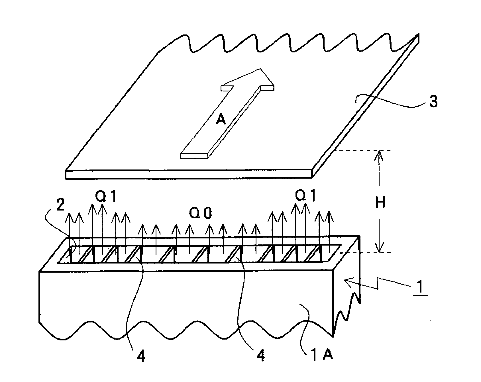
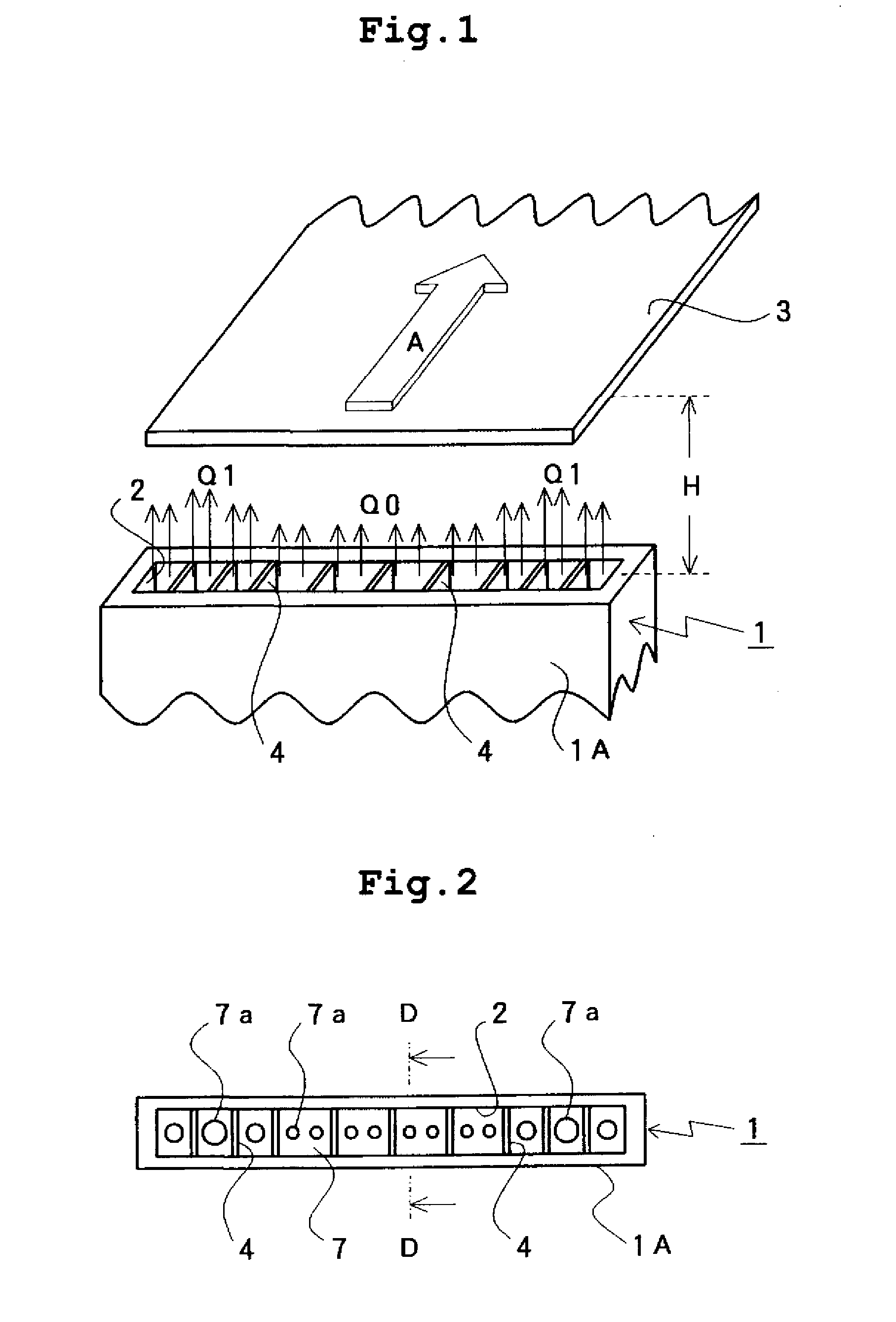
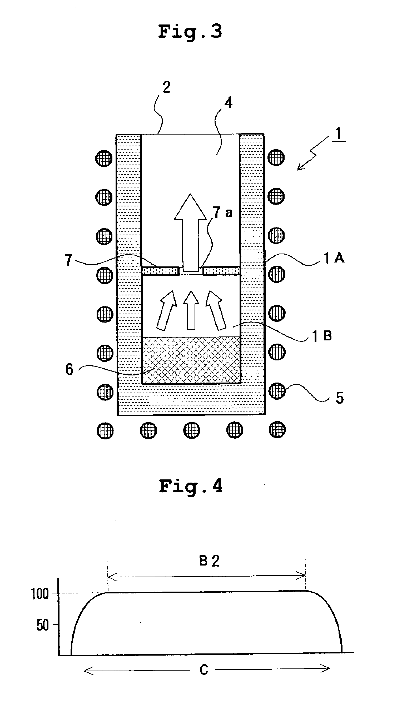
[0039]An evaporation source according to the present invention and a vacuum evaporator using the same will be described below on the basis of illustrated embodiments. FIG. 1 to FIG. 3 schematically show a vacuum evaporator according to the present invention. FIG. 1 shows the constitution of an evaporation source and a deposited substrate that faces and is immediately above the evaporation source and is transferred in one direction, FIG. 2 is a top view when the evaporation source is viewed from immediately above a nozzle opening, and FIG. 3 shows an enlarged sectional view of the evaporation source when viewed in the arrow direction from the D-D line in FIG. 2.

[0040]In FIG. 1, components performing similar functions to those of components described in FIG. 13 are shown with the same reference numerals. That is, reference numeral 1 shows an evaporation source and reference numeral 1A shows a long cabinet part constituting a contour of the evaporation source 1. Further, reference nume...

second embodiment

[0063]Next, FIG. 7 and FIG. 8 show the vacuum evaporator, particularly the evaporation source according to the present invention. FIG. 7 shows an upper part of the cabinet part 1A constituting the evaporation source 1 and FIG. 8 is an enlarged sectional view of the evaporation source 1 when viewed in the arrow direction from the E-E line in FIG. 7. In FIG. 7 and FIG. 8, the same reference numerals are attached to components corresponding to components already described based on figures to omit a duplicate description.

[0064]In the present embodiment, more straightening plates 4a are arranged in vertical and horizontal directions like a grid in each nozzle opening with a smaller caliber partitioned by each partition plate 4 arranged in the nozzle opening 2 and the nozzle opening 2 is partitioned into paths of still smaller caliber by the straightening plates 4a.

[0065]Meanwhile, in the present embodiment, a space part 8 is formed between the many straightening plates 4a and the contro...

third embodiment

[0067]FIG. 9 shows the vacuum evaporator, particularly the evaporation source according to the present invention and shows, like FIG. 2 already described, when the evaporation source is viewed from immediately above the nozzle opening. In the present embodiment, the control plate 7 arranged to partition the cabinet part 1A constituting the evaporation source 1 into upper and lower portions has the vapor passage holes 7a having approximately the same diameter drilled along the longitudinal direction of the control plate 7 in a line. Then, the arrangement pitch of the vapor passage holes 7a is made narrower in the both edge parts than in the central part of the control plate 7.

[0068]Then, the many partition plates 4 arranged in the nozzle opening 2 are arranged in such a way that the nozzle opening 2 is partitioned into many nozzle openings having a smaller caliber with one vapor passage hole 7a positioned in the center and, as a result, the arrangement pitch of the partition plates 4...


PUM

PropertyMeasurementUnit
width sizeaaaaaaaaaa

Abstract

An evaporation source having a nozzle structure that makes the distribution of film thickness uniform in the width direction of a substrate and a vacuum evaporator using the same are provided. A vapor produced by evaporation or sublimation by heating to evaporation material is discharged from a long nozzle opening like a band. A deposited substrate is transferred in a direction perpendicular to the longitudinal direction of the nozzle opening while facing the nozzle opening. A discharge flow rate of vapor per unit area in the longitudinal direction of the nozzle opening is made to be maximum in a portion at a nozzle width direction position corresponding to a substrate edge position rather than a central part of the nozzle opening and a plurality of partition plates providing directivity to the flow of vapor are arranged inside the nozzle opening.

Description

BACKGROUND OF THE INVENTION[0001]1. Field of the Invention[0002]The present invention relates to an evaporation source having a nozzle structure that is suitable for continuously forming a thin film on a deposited substrate by vapor deposition and a vacuum evaporator using the same.[0003]2. Description of the Related Art[0004]As is well-known, a vacuum evaporator causes a thin film to be formed by arranging an evaporation material and a deposited substrate in a vacuum chamber, melting the evaporation material by heating to cause vaporization through evaporation or sublimation, and causing the vaporized evaporation material to be deposited on the surface of a deposited substrate. Heater heating, high-frequency heating, beam heating and the like have been proposed as heating methods of the evaporation material in the above-mentioned vacuum evaporator and, though each heating method has its own special features, generally an external heating crucible method by which a vaporizing chambe...

Claims


Application Information

Patent Timeline
Patent Type & Authority Applications(United States)
IPC IPC(8): C23C16/00
CPCC23C14/243C23C14/542C23C14/26C23C14/24
Inventor ODA, ATSUSHIKOBAYASHI, TOSHIROSATO, KEIICHIKITAMOTO, HIROKOKAMIKAWA, SUSUMUWADA, KOZO
Owner MITSUBISHI HEAVY IND LTD
Why Eureka
Try Eureka