
High impact resistant tool

a tool and high impact resistance technology, applied in the field of high impact resistance tools, can solve the problems of reducing or eliminating the efficacy of cutting elements, high temperature and temperature differentials, and inconvenient use, and achieve the effect of high impact resistan

Active Publication Date: 2009-09-15
SCHLUMBERGER TECH CORP
View PDF124 Cites 74 Cited by
  • Summary
  • Abstract
  • Description
  • Claims
  • Application Information

AI Technical Summary

Benefits of technology

The tool achieves increased impact strength and wear resistance, with the ability to withstand significant impacts and maintain effectiveness over a longer working life by minimizing stress and delamination through controlled sintering and metal distribution.

Problems solved by technology

Such inserts are often subjected to intense forces, torques, vibration, high temperatures and temperature differentials during operation.
As a result, stresses within the structure may begin to form.
Drill bits for example may exhibit stresses aggravated by drilling anomalies during well boring operations such as bit whirl or bounce often resulting in spalling, delamination or fracture of the super hard abrasive layer or the substrate thereby reducing or eliminating the cutting elements efficacy and decreasing overall drill bit wear life.
Damage typically found in percussive and drag bits may be a result of shear failures, although non-shear modes of failure are not uncommon The interface between the superhard material layer and substrate is particularly susceptible to non-shear failure modes due to inherent residual stresses.

Method used


Image

  • High impact resistant tool
  • High impact resistant tool
  • High impact resistant tool

Examples


Embodiment Construction

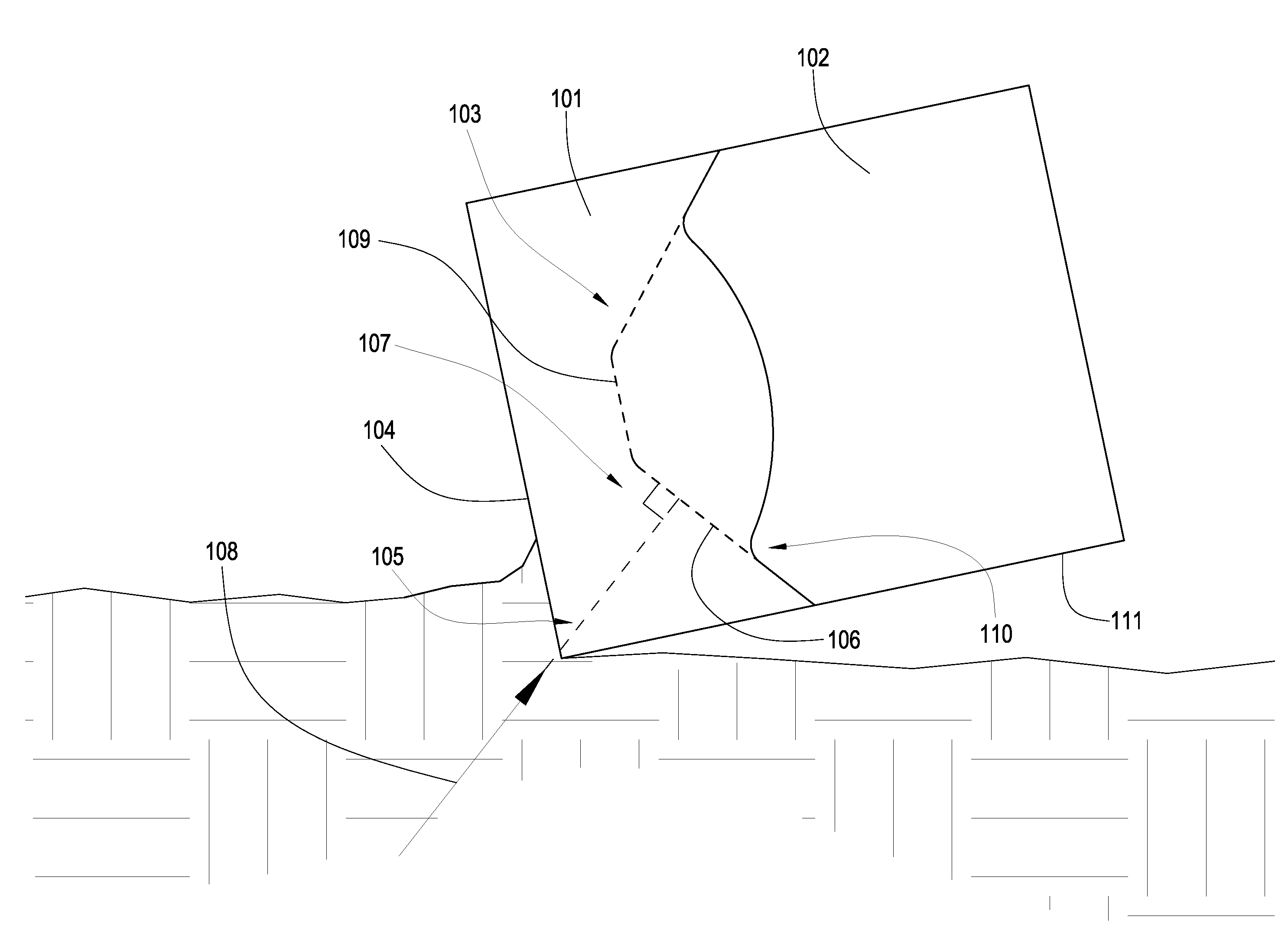
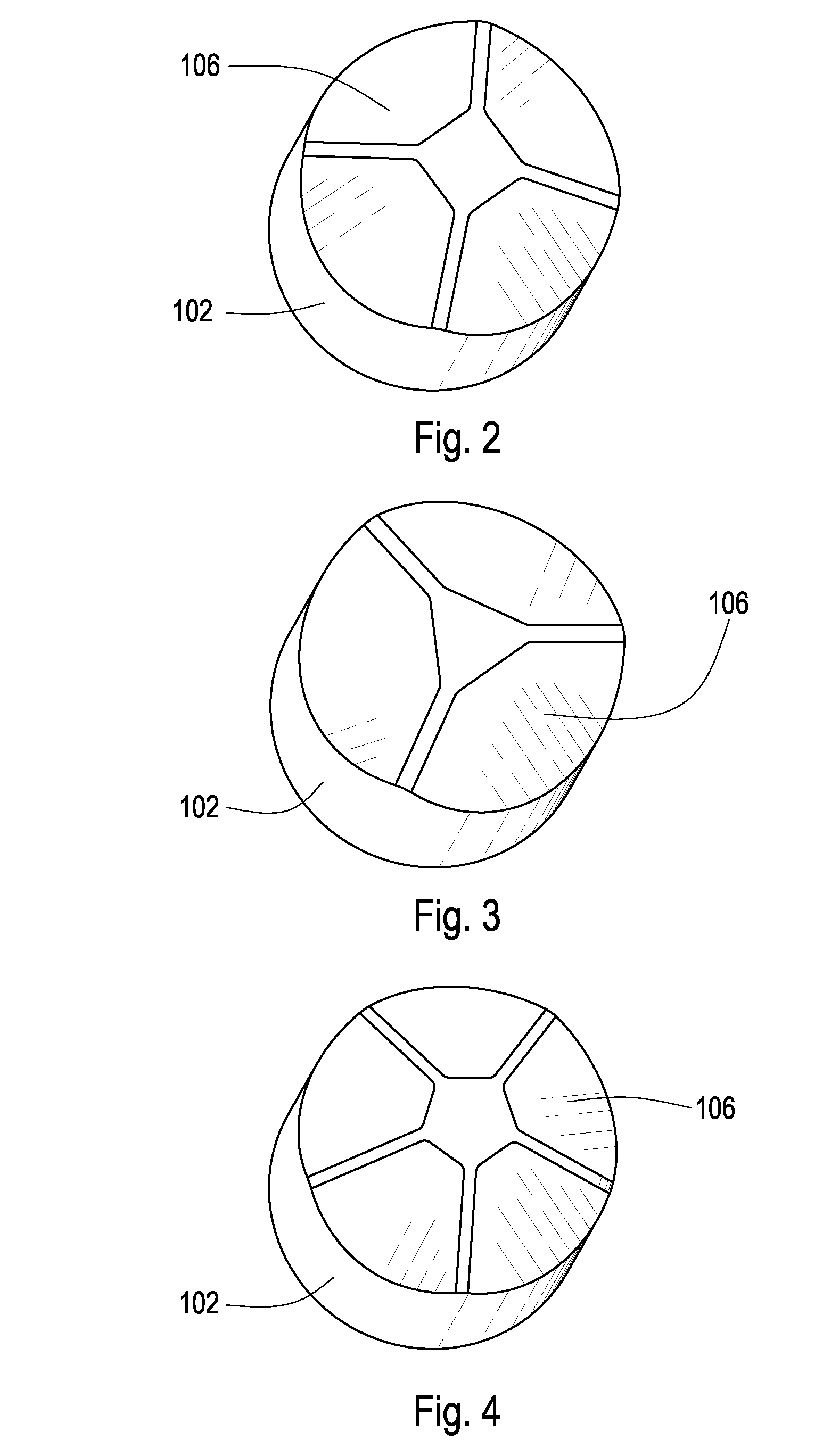
[0035]FIG. 1 discloses an embodiment of a high impact resistant tool 100 which may be used in machines in mining, downhole drilling, asphalt milling, or trenching industries. The high impact resistant tool comprises a sintered body 101 of diamond or diamond-like particles in a metal matrix bonded to a cemented metal carbide substrate 102 at a non-planar interface 103, a hidden portion of which is shown by the dashed line. The body 101 comprises a working surface 104 used to abrade or degrade road surfaces, downhole rock and earth formations, or other materials.

[0036]The amount of metal in the body 101 of the high impact resistant tool 100 may be vital to the working life of the tool 100, particularly in regions near the working surface 104. At least one region 105 of the working surface 104 is far enough away from the non-planar interface 103 that during high pressure, high temperature (HPHT) processing a restricted amount of metal from the substrate reaches the region 105, the amou...


PUM

PropertyMeasurementUnit
timeaaaaaaaaaa
radiusaaaaaaaaaa
angleaaaaaaaaaa

Abstract

A tool has a sintered body of diamond or diamond-like particles in a metal matrix bonded to a cemented metal carbide substrate at a non-planar interface. A working surface has at least one region fir enough away from the non-planar interface that during high pressure, high temperature processing a restricted amount of metal from the substrate reaches the region, the amount comprising 5 to 0.1 percent of the region by volume, resulting in the region having a high density of superhard particles.

Description

[0001]This application is a continuation in-part of U.S. patent application Ser. No. 11 / 673,634 filed on Feb. 12, 2007 entitled Thick Pointed Superhard Material. U.S. patent application Ser. No. 11 / 673,634 is a continuation in-part of U.S. patent application Ser. No. 11 / 668,254 which was filed on Jan. 29, 2007 now U.S. Pat. No 7,353,893 and entitled A Tool with a Large Volume of a Superhard Material. U.S. patent application Ser. No. 11 / 668,254 is a continuation in-part of U.S. patent application Ser. No. 11 / 553,338 which was filed on Oct. 26, 2006 and was entitled Superhard Insert with an Interface. Both of these applications are herein incorporated by reference for all that they contain and are currently pending.BACKGROUND OF THE INVENTION[0002]The invention relates to a high impact resistant tool that may be used in machinery such as crushers, picks, grinding mills, roller cone bits, rotary fixed cutter bits, earth boring bits, percussion bits or impact bits, and drag bits. More p...

Claims


Application Information

Patent Timeline
Patent Type & Authority Patents(United States)
IPC IPC(8): E21B10/46
CPCE21B10/5673E21B10/5735E21B10/5676
Inventor HALLCROCKETT, RONALD B.
Owner SCHLUMBERGER TECH CORP
Learn More