
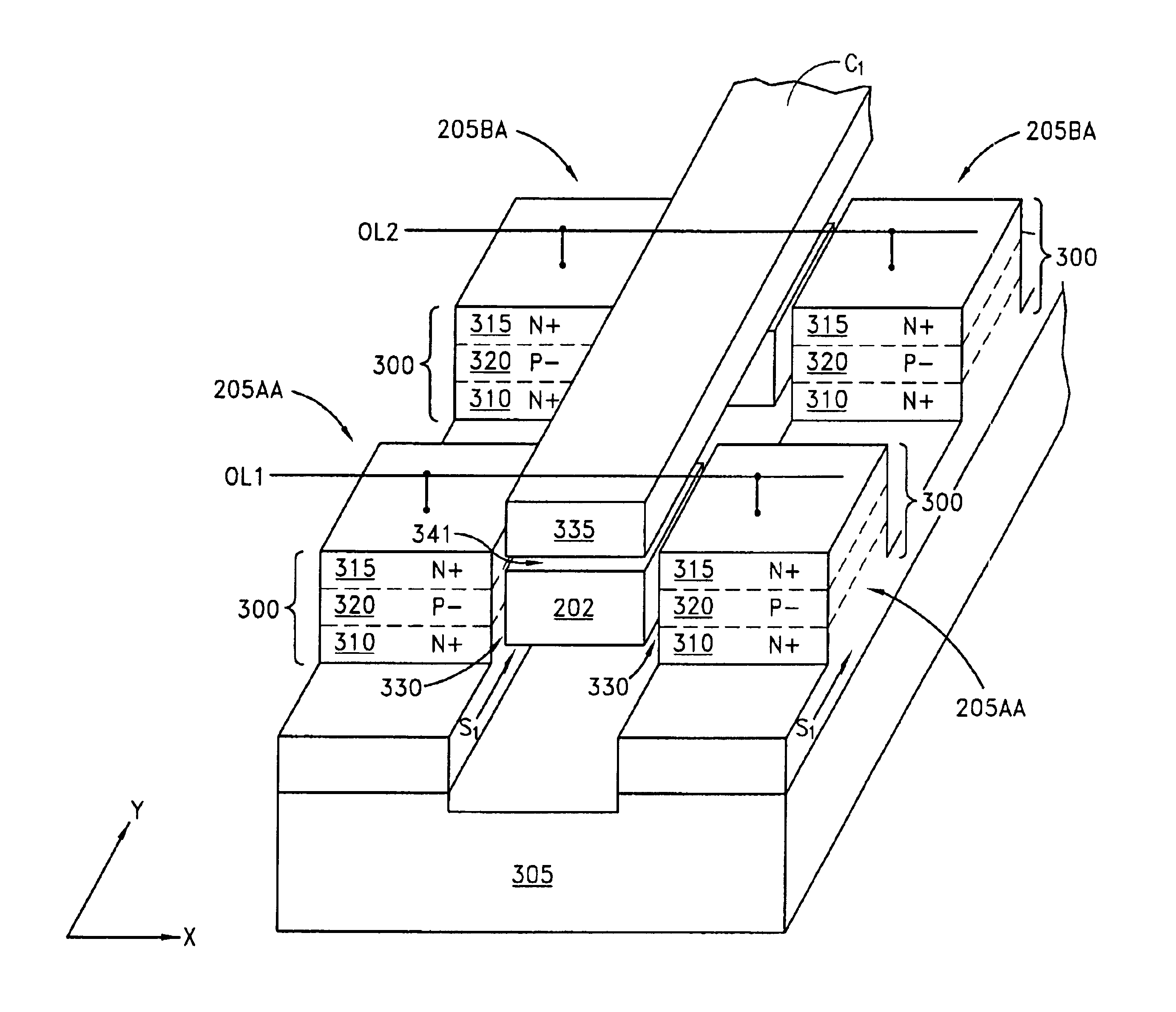
Floating gate transistor with horizontal gate layers stacked next to vertical body

a floating gate transistor and horizontal gate technology, applied in the field of integrated circuits, can solve problems such as limiting circuit density

Inactive Publication Date: 2004-06-01
MICRON TECH INC
View PDF26 Cites 341 Cited by
  • Summary
  • Abstract
  • Description
  • Claims
  • Application Information

AI Technical Summary

Benefits of technology

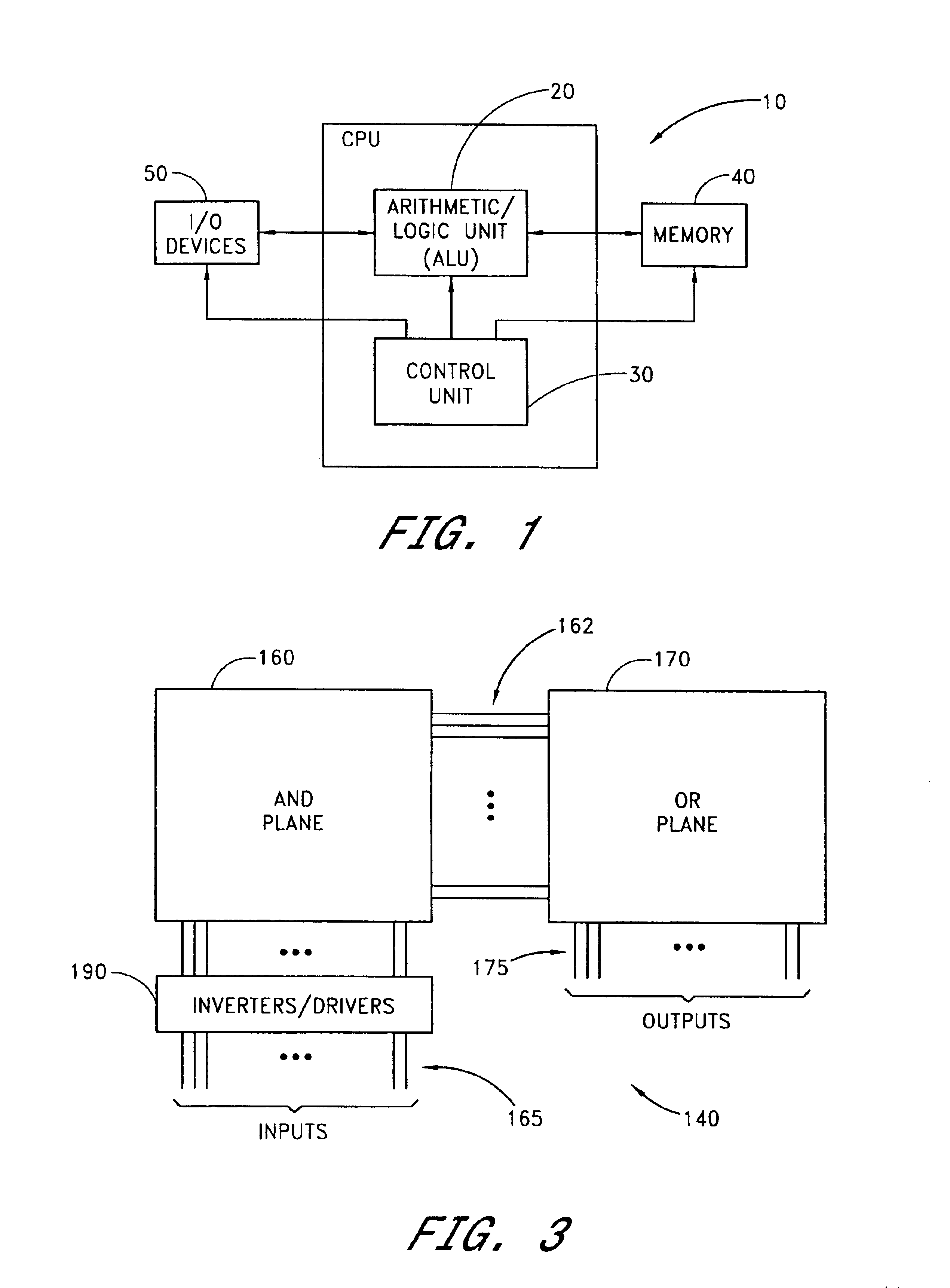
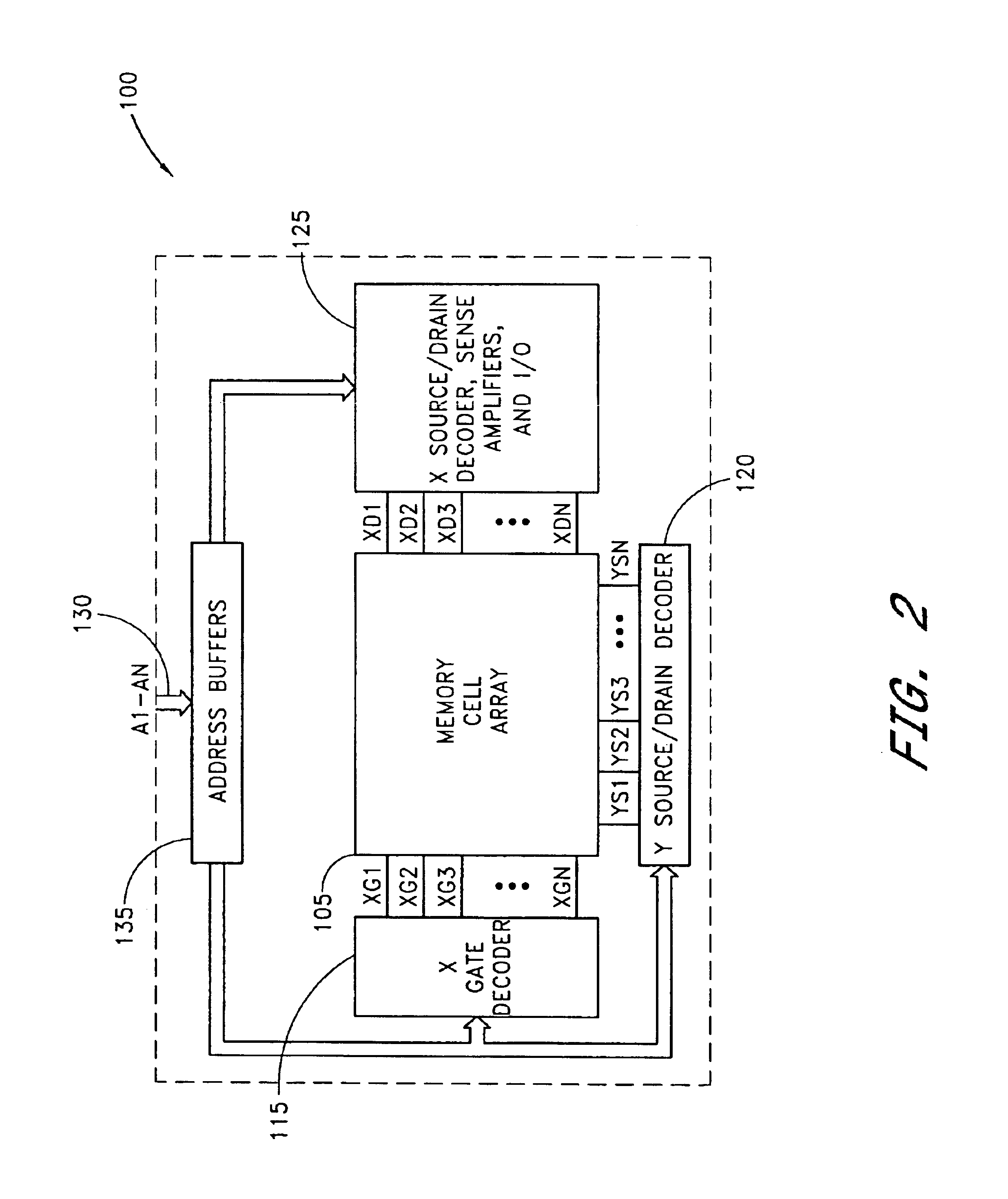
The present invention provides a new type of floating gate transistor with vertical bodies and horizontal gates stacked next to each other. This new transistor structure allows for higher circuit density in programmable memories and logic circuits. The transistor includes a pillar of semiconductor material with a source region, body region, and drain region. A floating gate forms a conductivity state in the transistor based on the presence or absence of stored charges in the floating gate. The transistor can be programmed using hot electron injection or Fowler-Nordheim tunneling. The transistor can be fabricated on a substrate and used in a memory cell array or logic array. The transistor structure allows for higher circuit density in programmable memories and logic circuits.

Problems solved by technology

A common problem among the programmable memories and the related FPLAs is a large cell size, which limits circuit density.

Method used


Image

  • Floating gate transistor with horizontal gate layers stacked next to vertical body
  • Floating gate transistor with horizontal gate layers stacked next to vertical body
  • Floating gate transistor with horizontal gate layers stacked next to vertical body

Examples


Embodiment Construction

In the following detailed description of the invention, reference is made to the accompanying drawings which form a part thereof, and in which is shown, by way of illustration, specific embodiments in which the invention may be practiced. In the drawings, like numerals describe substantially similar components throughout the several views.

In the following description, the terms wafer and substrate are interchangeably used to refer generally to any structure on which integrated circuits (ICs) are formed, and also to such structures during various stages of integrated circuit fabrication. Both wafer and substrate include doped and undoped semiconductors, epitaxial semiconductor layers supported by a base semiconductor or insulator, combinations of such layers, as well as other semiconductor structures well known to one skilled in the art, including bulk semiconductor and semiconductor-on-insulator (SOI) substrates. The term conductor is understood to include semiconductors, and the te...


PUM


Abstract

Vertical body transistors with adjacent horizontal gate layers are used to form a memory array in a high density flash electrically erasable and programmable read only memory (EEPROM) or a logic array in a high density field programmable logic array (FPLA). The transistor is a field-effect transistor (FET) having an electrically isolated (floating) gate that controls electrical conduction between source regions and drain regions. If a particular floating gate is charged with stored electrons, then the transistor will not turn on and will provide an indication of the stored data at this location in the memory array within the EEPROM or will act as the absence of a transistor at this location in the logic array within the FPLA. The memory array or the logic array includes densely packed cells, each cell having a semiconductor pillar providing shared source and drain regions for two vertical body transistors that have control gates overlaying floating gates distributed on opposing sides of the semiconductor pillar. Both bulk semiconductor and silicon-on-insulator embodiments are provided. If a floating gate transistor is used to store a single bit of data or to represent a logic function, an area of only 2F<2 >is needed per respective bit of data or bit of logic, where F is the minimum lithographic feature size.

Description

1. Field of the InventionThis invention relates generally to integrated circuits and in particular to floating gate transistors.2. Description of the Related ArtProgrammable memories and logic circuits are integral parts of a digital system, such as a computer, and can have similar physical structures. One type of programmable memories is an electrically erasable and programmable read only memory (EEPROM), which is a reprogrammable nonvolatile memory that is widely used in the computer system for storing data both when power is supplied or removed. The typical data storage element of an EEPROM is a floating gate transistor, which is a field-effect transistor (FET) having an electrically isolated (i.e., floating) gate that controls electrical conduction between source and drain regions. Data is represented by charges stored on the floating gate and the resulting conductivity obtained between the source region and the drain region.Recently, logic circuits based on programmable memorie...

Claims


Application Information

Patent Timeline
Patent Type & Authority Patents(United States)
IPC IPC(8): H01L29/66H01L27/115H01L29/788G11C16/04H10B69/00
CPCG11C16/0408H01L21/28273H01L27/115H01L27/11521H01L29/42336H01L29/66825H01L29/7881H01L29/7885G11C16/0416H01L29/40114H10B69/00H10B41/30
Inventor FORBES, LEONARD
Owner MICRON TECH INC
Learn More