
Heating member for an image forming apparatus, having improved releasibility and conductivity

a technology of image forming apparatus and heating member, which is applied in the direction of electrographic process, instruments, transportation and packaging, etc., can solve the problems of degrading thermal conductive efficiency, affecting the releasability of fixing roller surface, and image may be stained, so as to improve the friction resistance property and thermal conductivity of surface layer, ensure the releasability of toner, and ensure the effect of releasability

Inactive Publication Date: 2009-07-07
RICOH KK
View PDF33 Cites 15 Cited by
  • Summary
  • Abstract
  • Description
  • Claims
  • Application Information

AI Technical Summary

Benefits of technology

The solution effectively reduces temperature lowering on the fixing member surface, enhances image forming stability, and prevents toner offset, achieving high durability and energy efficiency in image forming processes.

Problems solved by technology

However, ordinarily, a fluorine coating on the order of 20 through 30 μm is required for maintaining release characteristics and durability, and this may degrade thermal conductive efficiency.
However, in the invention described in Patent Document 1, since merely fluorocarbon particles are mixed into a nickel layer, releasability of a fixing roller surface may not be sufficient, and offset may occur so that an image may be stained.
Further, in a heating method with the use of electromagnetic induction, eddy current is required to flow, and thus, sufficient heating may not be expected in an electric conductor separated by an insulator.
Thus, improvement in thermal conductivity is limited.
Thus, it is not possible to apply it to a fixing roller.
As a result, magnetic particles having insufficient releasability gather on a surface which needs releasability when this method is applied to a releasable layer, and thus, it is not possible to ensure releasability.
Thus, it is not possible to apply it to a fixing roller.
Further, melted metal does not easily cause fluorocarbon resin to get wet therewith, metal agglutinates when the metal is added in a volume ratio necessary to improve the thermal conductivity.
Thereby, releasability is lost.
Therefore, when applying the same configuration to a fixing member, softened toner's adhesion occurs, and thus, it is not possible to apply.
Therefore, it is difficult to produce a uniform configuration with the use of resin (which is not easily impregnated since it has a high viscosity) having a high melting point on a roller or on a belt.

Method used


Image

  • Heating member for an image forming apparatus, having improved releasibility and conductivity
  • Heating member for an image forming apparatus, having improved releasibility and conductivity
  • Heating member for an image forming apparatus, having improved releasibility and conductivity

Examples


embodiment 1

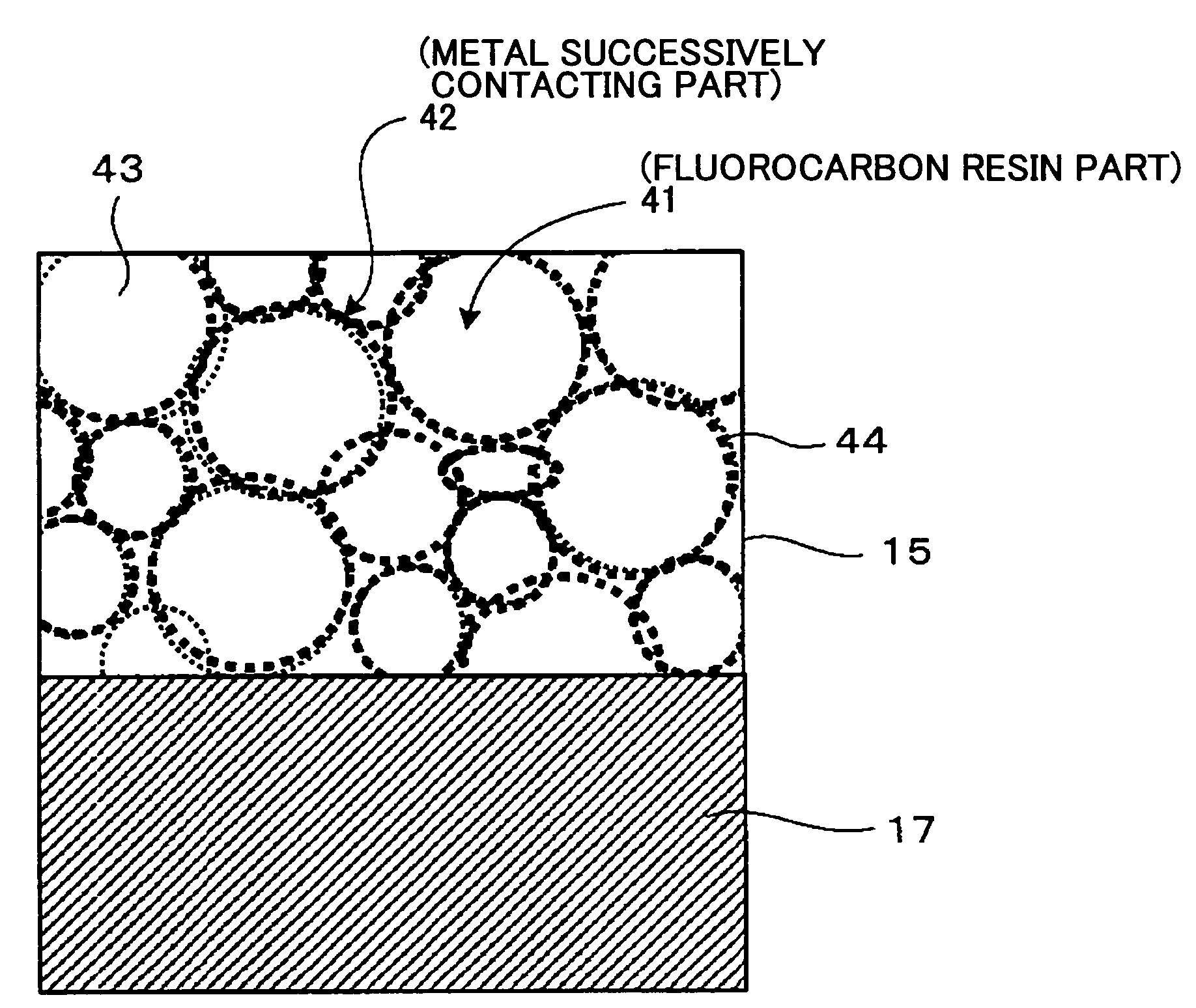
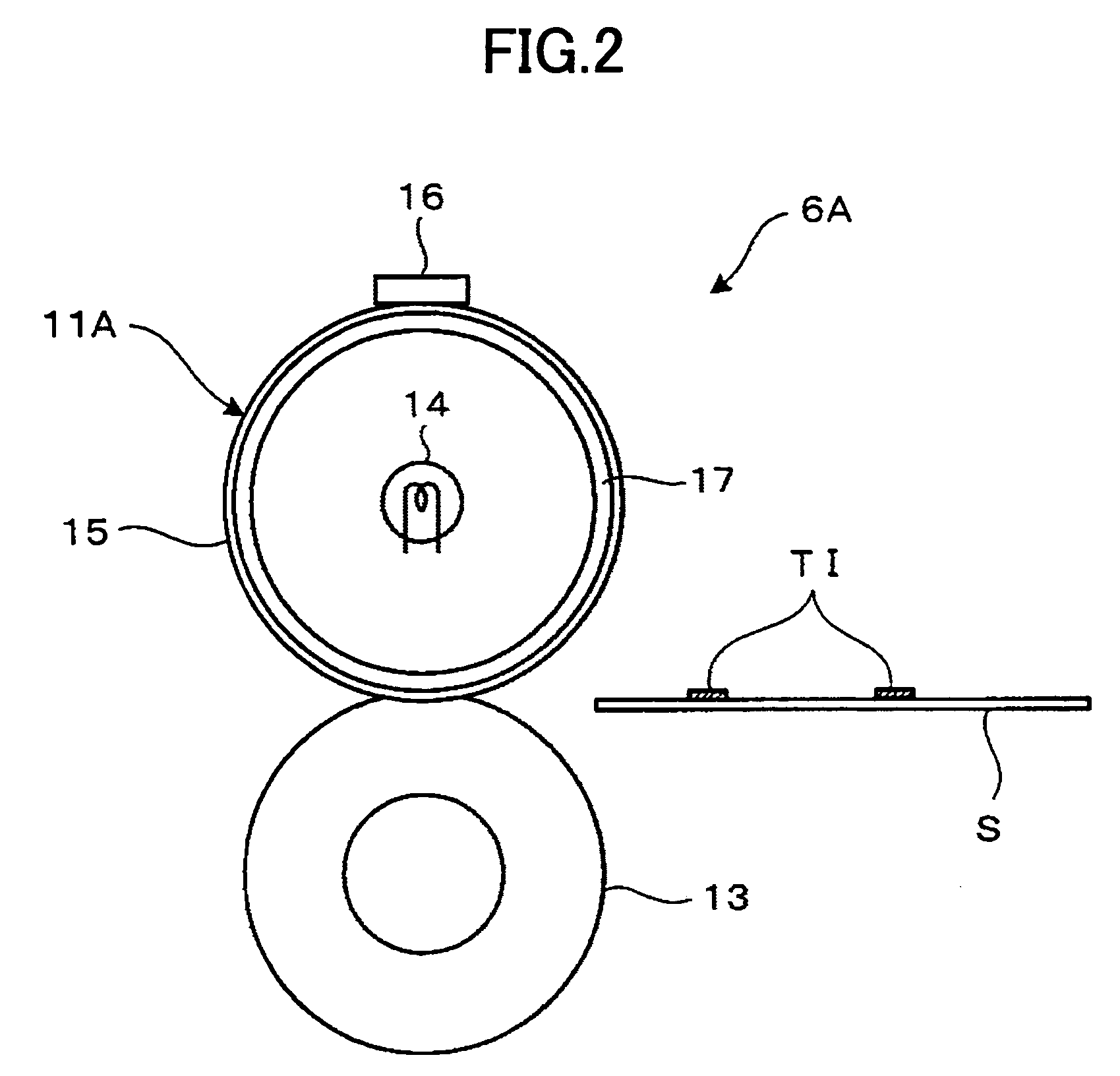
[0485]First, embodiments of the heating member (fixing member) 11A having the surface layer 15 having a configuration shown in FIGS. 6 and 7 used in the fixing device 6A configured as shown in FIG. 2 are described.

embodiment 1-1

[0486]As a component of the surface layer, Ni powder (average particle diameter: 1.2 μm) was mixed into PFA powder (MP102 (made by DuPont-Mitsui Fluorochemicals Co., Ltd.), average particle diameterφ: 20 μm) in an amount such that Ni is 10% in reduced volume, the thus-obtained one was input to a hybridization system configured as shown in FIG. 8 made by Nara Machinery, and Ni powder was fixed on PFA powder. A state in which Ni almost covered PFA powder was confirmed from observation by means of a scanning electron microscope (SEM). This powder was mixed with PFA powder (MP102 (DuPont-Mitsui Fluorochemicals Co., Ltd.), average particle diameter φ: 20 μm), was coated on an aluminum substrate in an electrostatic manner, burning was carried out at 380° C., resin was melted and then cooled, the coating was pealed from the substrate, and a sample was produced. Thus, a sheet having a thickness of 100 μm was produced, and thermal diffusivity was measured according to a laser flash method. T...

embodiment 1-2

[0488]The same as the embodiment 1-1, as a component of the surface layer, Ni powder (average particle diameter: 1.2 μm) was mixed into PFA powder (MP102 (made by DuPont-Mitsui Fluorochemicals Co., Ltd.), average particle diameterφ: 20 μm) in an amount such that Ni is 10% in reduced volume, the thus-obtained one was input to a hybridization system configured as shown in FIG. 8 made by Nara Machinery, and Ni powder was fixed on PFA powder. Then, mixing was carried out according to a ratio of Table 3 below, coating was carried out on an aluminum tube to be the core metal (base material) 17 of the fixing roller in an electrostatic manner, the coated resin was melted at 380° C. and then cooled, grinding was carried out by means of corundum particles, thus one on which surface roughness was made equal to or less than 2 μm in ten-point average roughness (Rz) was produced, and thus, the fixing roller 11A was produced. A final thickness of the surface layer is 40 μm. This roller was loaded ...


PUM

PropertyMeasurementUnit
roughnessaaaaaaaaaa
melting pointaaaaaaaaaa
temperatureaaaaaaaaaa

Abstract

The present invention is characterized in that, for the purpose of achieving a heating member (fixing member) in which thermal conductivity or electrical conductivity is given to a resin surface layer without loss of releasability, and heating efficiently is improved, the heating member contacting a to-be-heated member and heating the same has a surface layer 15 in which, in a resin material 43 having releasability, a material (for example, metal) 44 having either one or both thermal conductivity and electrical conductivity is mixed, and the material contact successively. Specifically, the heating member (fixing member) according to the present invention has the surface layer 15 in which the metal 44 is mixed into the fluorocarbon resin 43, and the metal 44 forms metal successively contacting part 42 in which the metal 44 successively contacts in such a manner as to surround the fluorocarbon resin part 41. Thereby, it is possible to improve thermal conductivity or electrical conductivity while maintaining releasability.

Description

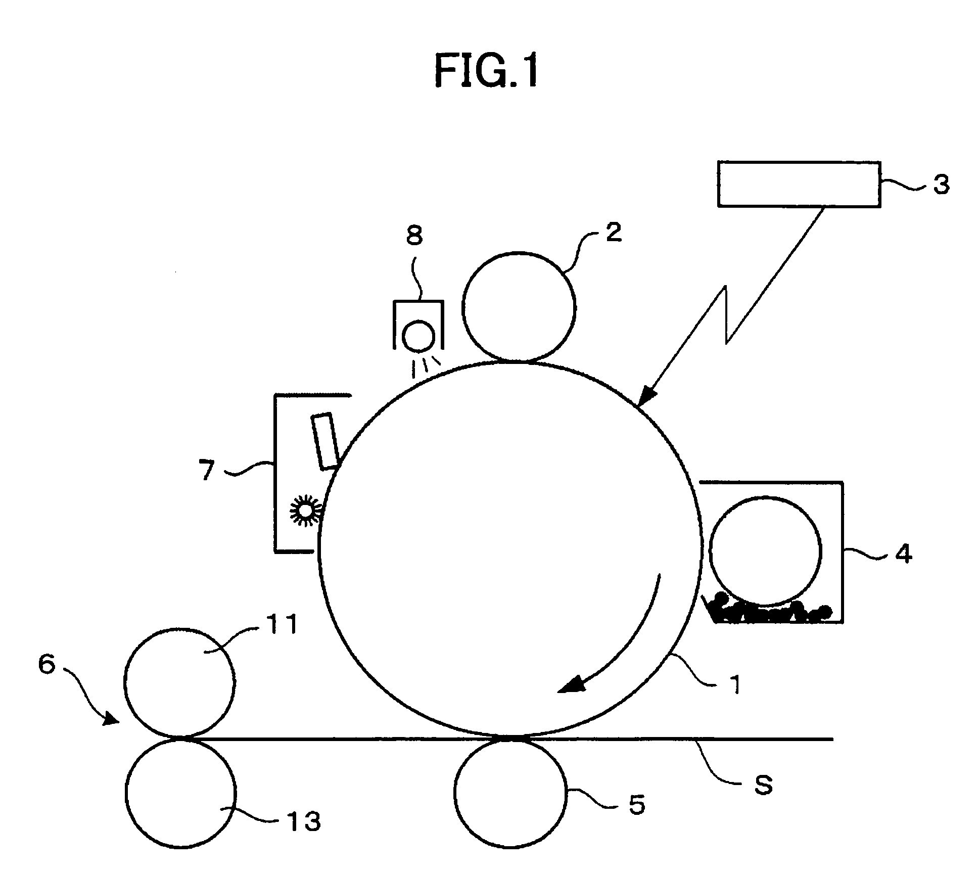
CROSS-REFERENCE TO RELATED APPLICATION[0001]This application is a U.S. continuation application filed under 35 USC 111(a) claiming benefit under 35 USC 120 and 365(c) of PCT application JP2004 / 015627, filed Oct. 21, 2004, which claims priority to Application Ser. No. 2003-364598 filed on Oct. 24, 2003; 2004-076530 filed on Mar. 17, 2004; and 2004-302585 filed on Oct. 18, 2004. The foregoing applications are hereby incorporated herein by reference.TECHNICAL FIELD[0002]The present invention relates to a heating member used in a heating device or a fixing device, for heating a to-be-heated member; the heating member surface layer producing method; a fixing member made of the heating member for fixing a non-fixed image onto a sheet-like to-be-heated member (recording material); a heating device employing the heating member; a fixing method and a fixing device employing the fixing member and fixing a non-fixed image to a recording material; and a fixing method and a fixing device employi...

Claims


Application Information

Patent Timeline
Patent Type & Authority Patents(United States)
IPC IPC(8): G03G15/20H05B3/00H05B6/02H05B6/10H05B6/14
CPCG03G15/2057G03G2215/2048Y10T428/3154
Inventor SUGAWARA, TOMOAKISATOH, TATSUYA
Owner RICOH KK
Learn More