Patterning method of liquid crystal display device

a liquid crystal display and patterning technology, applied in the direction of liquid/solution decomposition chemical coating, superimposed coating process, instruments, etc., can solve the problems of increasing the time required for manufacturing lcd devices, photolithography has the disadvantage of increasing manufacturing costs, and photolithography requires complex exposure and development processes, so as to prevent a pattern material and achieve the effect of precise patterning

Inactive Publication Date: 2009-06-09
LG DISPLAY CO LTD
View PDF4 Cites 1 Cited by
  • Summary
  • Abstract
  • Description
  • Claims
  • Application Information

AI Technical Summary

Benefits of technology

[0019]An advantage of the present invention is to provide a patterning method of a liquid crystal display (LCD) device, to prevent a pattern material from having a swelling portion when using a printing method, thereby obtaining preciseness in patterning.
[0020]Additional features and advantages of the invention will be set forth in part in the description which follows and in part will become apparent to those having ordinary skill in the art upon examination of the following or may be learned from practice of the invention. The objectives and other advantages of the invention may be realized and attained by the structure particularly pointed out in the written description and claims hereof as well as the appended drawings.
[0021]To achieve these and other advantages and in accordance with the purpose of the invention, as embodied and broadly described herein, a patterning method includes a first step for coating a pattern material containing charged particles onto a printing roll having a blanket adhered thereto wherein the charged particles give the pattern material a polarity; a second step for rolling the printing roll on a printing plate having a plurality of projections to print some pattern material onto the projections of the printing plate and leaving remaining pattern material on the blanket to form a predetermined pattern on the blanket of the printing roll with the remaining pattern material; and a third step for rolling the printing roll on a substrate to re-print the predetermined pattern of pattern material onto the substrate, wherein the first step includes applying a voltage to the printing roll having a polarity opposite to the pattern material.
[0022]In another aspect of the present invention, a patterning method includes a first step for coating a pattern material containing charged particles in a plurality of recesses of a printing plate wherein the charged particles give the pattern material a polarity; a second step for rolling a printing roll having a blanket adhered thereto on the printing plate to print the pattern material formed in the plurality of recesses onto the printing roll to form a predetermined pattern of the pattern material on the printing roll; and a third step for rolling the printing roll on a substrate to re-print the predetermined pattern of the printing roll onto the substrate, wherein the second step includes applying a voltage to the printing roll having a polarity opposite to the pattern material.
[0023]In another aspect of the present invention, a patterning method includes a first step for coating a pattern material containing charged particles on a printing plate wherein the charged particles give the pattern material a polarity; a second step for rolling a printing roll having a plurality of projections and a blanket adhered thereto on the printing plate having the pattern material to form a predetermined shape of the pattern material on the printing roll by printing some pattern material onto the blanket over the projections; and a third step for rolling the printing roll on a substrate to re-print the predetermined shape of the pattern material onto the substrate, wherein the second step includes applying a voltage to the printing roll having a polarity opposite to the pattern material.
[0024]In another aspect of the present invention, a patterning method includes a first step for coating a pattern material containing charged particles on a printing roll having a blanket adhered thereto, wherein the charged particles give the pattern material a polarity, and wherein a voltage of the opposite polarity to the pattern material is applied to the printing roll; a second step for rolling the printing roll on a printing plate having a plurality of projections to print some of the pattern material onto the projections of the printing plate and leaving remaining pattern material on the blanket to form a predetermined pattern on the blanket of the printing roll with the remaining pattern material, wherein a voltage of the same polarity as the pattern material is applied to the printing roll, and a voltage of the opposite polarity to the pattern material is applied to the printing plate; and a third step for rolling the printing roll on a substrate to re-print the predetermined pattern of pattern material onto the substrate, wherein a voltage of the same polarity as the pattern material is applied to the printing roll, and a voltage of the opposite polarity to the pattern material is applied to the substrate.

Problems solved by technology

Accordingly, photolithography has the disadvantage of increasing manufacturing cost.
In addition, photolithography requires complex exposure and development processes increasing the time required for manufacturing LCD devices.
Printing methods employ physical contact between the printing roll and the substrate, which can restrict the applicability of the printing method.
When the related art printing method is used, problems associated with the blanket 35 adhering to the printing roll 30 may interfere with precisely forming a required pattern on the substrate 50.
However, Si-based resin has a low surface tension.
The swelling portion ‘A’ of the pattern material interferes with obtaining precise patterns using the printing method of the related art.

Method used


Image

  • Patterning method of liquid crystal display device
  • Patterning method of liquid crystal display device
  • Patterning method of liquid crystal display device

Examples


first embodiment

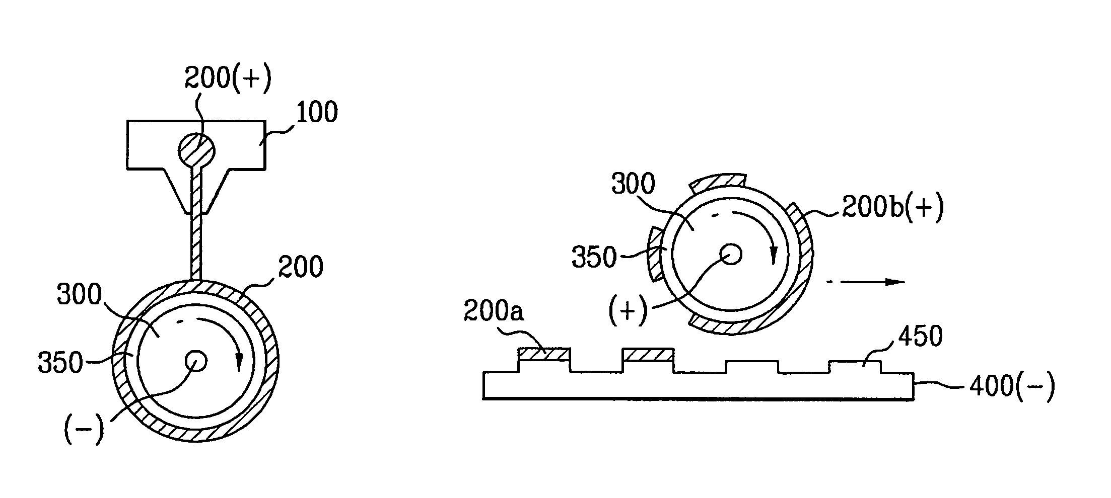
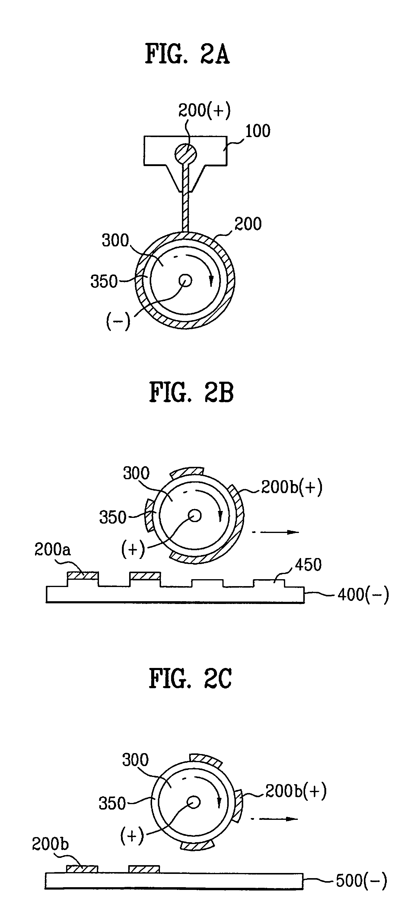
[0034]FIGS. 2A to 2C are schematic views illustrating a patterning method according to the present invention.

[0035]As shown in FIG. 2A, a pattern material 200 is supplied through a printing nozzle 100, and is coated on a printing roll 300 having a blanket 350 adhered thereto. The pattern material 200 contains positive (+) charged particles giving the pattern material a positive polarity, and a negative (−) voltage is applied to the printing roll 300 giving the printing roll a negative polarity. That is, the particles of the pattern material are opposite in polarity to the voltage applied to the printing roll 300. Even though the blanket 350 adhered to the printing roll 300 has a small surface tension, the pattern material 200 is uniformly coated on the printing roll 300 without swelling owing to an attractive force generated between the pattern material 200 and the printing roll 300.

[0036]As shown in FIG. 2B, as the printing roll 300 rolls on a printing plate 400 having a plurality ...

second embodiment

[0039]FIGS. 3A to 3C are schematic views illustrating a patterning method according to the present invention.

[0040]As shown in FIG. 3A, a pattern material 200 is coated in a plurality of recesses of a printing plate 400. The pattern material 200 contains positive (+) charged particles giving the pattern material a positive polarity.

[0041]Then, as shown in FIG. 3B, as a printing roll 300 having a blanket 350 adhered thereto rolls on the printing plate 400, the pattern material 200 coated in the recesses of the printing plate 400 is printed onto the blanket 350 of the printing roll 300. Accordingly, a predetermined shape of the pattern material 200 is formed on the blanket 350 of the printing roll 300.

[0042]A negative (−) voltage having opposite polarity to the pattern material 200 may be applied to the printing roll 300 to generate an attractive force between the printing roll 300 and the pattern material 200. The pattern material 200 of the printing plate 400 is more effectively pri...

third embodiment

[0047]FIGS. 4A to 4C are schematic views illustrating a patterning method according to the present invention.

[0048]As shown in FIG. 4A, a pattern material 200 is coated on a printing plate 400. The pattern material 200 contains positive (+) charged particles.

[0049]As shown in FIG. 4B, a plurality of projections 320 are formed on a printing roll 300 and a blanket 350 is adhered the printing roll. By rolling the printing roll 300 on the printing plate 400 having the pattern material 200 coated thereon, the pattern material 200 of the printing plate 400 is printed onto the blanket 350 over the projections 320, thereby forming a predetermined pattern 200b of the pattern material.

[0050]A negative (−) voltage having opposite polarity to the pattern material 200 is applied to the printing roll 300 to generate an attractive force between the printing roll 300 and the pattern material 200. The attractive force results in the pattern material 200 being more precisely printed onto the printing...


PUM

PropertyMeasurementUnit
polarityaaaaaaaaaa
voltageaaaaaaaaaa
shapeaaaaaaaaaa

Abstract

A patterning method of a liquid crystal display (LCD) device is disclosed, to prevent a pattern material from having a swelling portion when using a printing method, thereby obtaining preciseness in patterning, the patterning method including a first step for coating a pattern material containing charged particles on a printing roll having a blanket adhered thereto; a second step for rolling the printing roll on a printing plate having a plurality of projections for printing some pattern material on the projections of the printing plate and form a predetermined pattern on the blanket of the printing roll with the pattern material remaining on the blanket; and a third step for rolling the printing roll on a substrate to re-print the predetermined pattern of pattern material on the substrate, wherein the first step includes applying a voltage of the opposite polarity to the pattern material to the printing roll.

Description

[0001]This application claims the benefit of Korean Patent Application No. P2005-22265, filed on Mar. 17, 2005, which is hereby incorporated by reference for all purposes as if fully set forth herein.BACKGROUND OF THE INVENTION[0002]1. Field of the Invention[0003]The present invention relates to a liquid crystal display (LCD) device, and more particularly, to a patterning method of a liquid crystal display (LCD) device.[0004]2. Discussion of the Related Art[0005]Among various ultra-thin flat type display devices, which include devices having a display screen with a thickness of not more than a few centimeters, a liquid crystal display (LCD) device can be widely used for notebook computers, monitors, aircraft, etc. since it has advantages such as low power consumption and portability.[0006]The LCD device includes lower and upper substrates facing each other at a predetermined interval therebetween, and a liquid crystal layer formed between the lower and upper substrates. Generally, t...

Claims


Application Information

Patent Timeline
Patent Type & Authority Patents(United States)
IPC IPC(8): B05D1/04B05D5/06
CPCH05K3/1266H05K3/1275H05K2203/0108H05K2203/0143H05K2203/0517H05K2203/105G02F1/1335
Inventor YOO, HONG SUK
Owner LG DISPLAY CO LTD
Why Eureka
Try Eureka