
Cutting elements and bits incorporating the same

a technology of cutting elements and bits, applied in earth drilling, drilling machines and methods, construction, etc., can solve the problems of deterioration of the polycrystalline diamond layer, substrate may not be fully cured, etc., and achieve the effect of improving the cutting efficiency of the cutting layer

Active Publication Date: 2009-03-24
SMITH INT INC
View PDF75 Cites 40 Cited by
  • Summary
  • Abstract
  • Description
  • Claims
  • Application Information

AI Technical Summary

Benefits of technology

The design enhances abrasion resistance, strength, and fracture toughness, reducing thermal mismatch issues and extending the operating life of the cutting layer by forming a lip with sharp edges that provides aggressive cutting while minimizing heat generation and wear.

Problems solved by technology

In other instances, the substrate may be not fully cured, i.e., it may be green.
Cobalt has a significantly different coefficient of thermal expansion as compared to diamond, and as such, upon heating of the polycrystalline diamond, the cobalt expands, causing cracking to form in the lattice structure, resulting in the deterioration of the polycrystalline diamond layer.

Method used


Image

  • Cutting elements and bits incorporating the same
  • Cutting elements and bits incorporating the same
  • Cutting elements and bits incorporating the same

Examples


Embodiment Construction

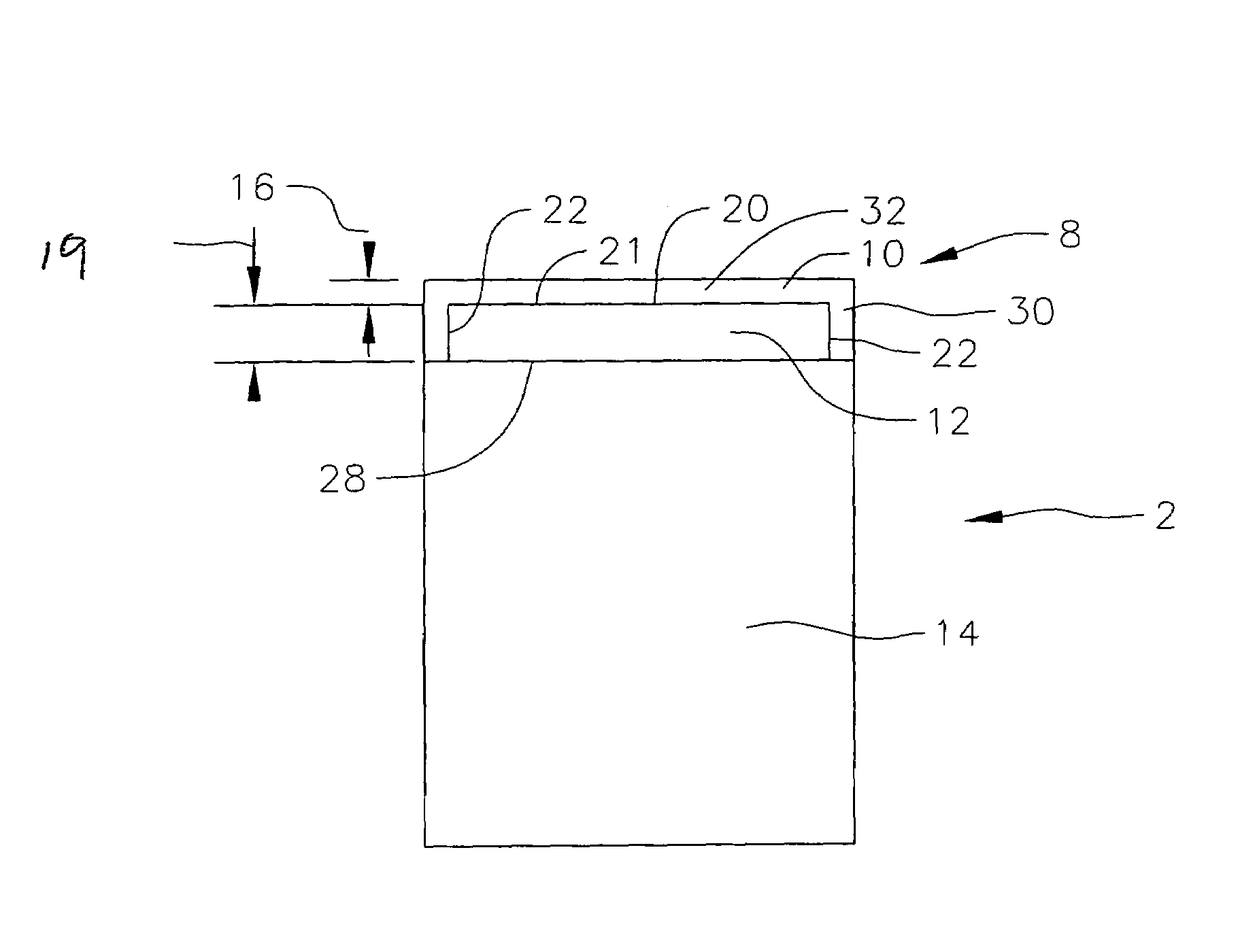
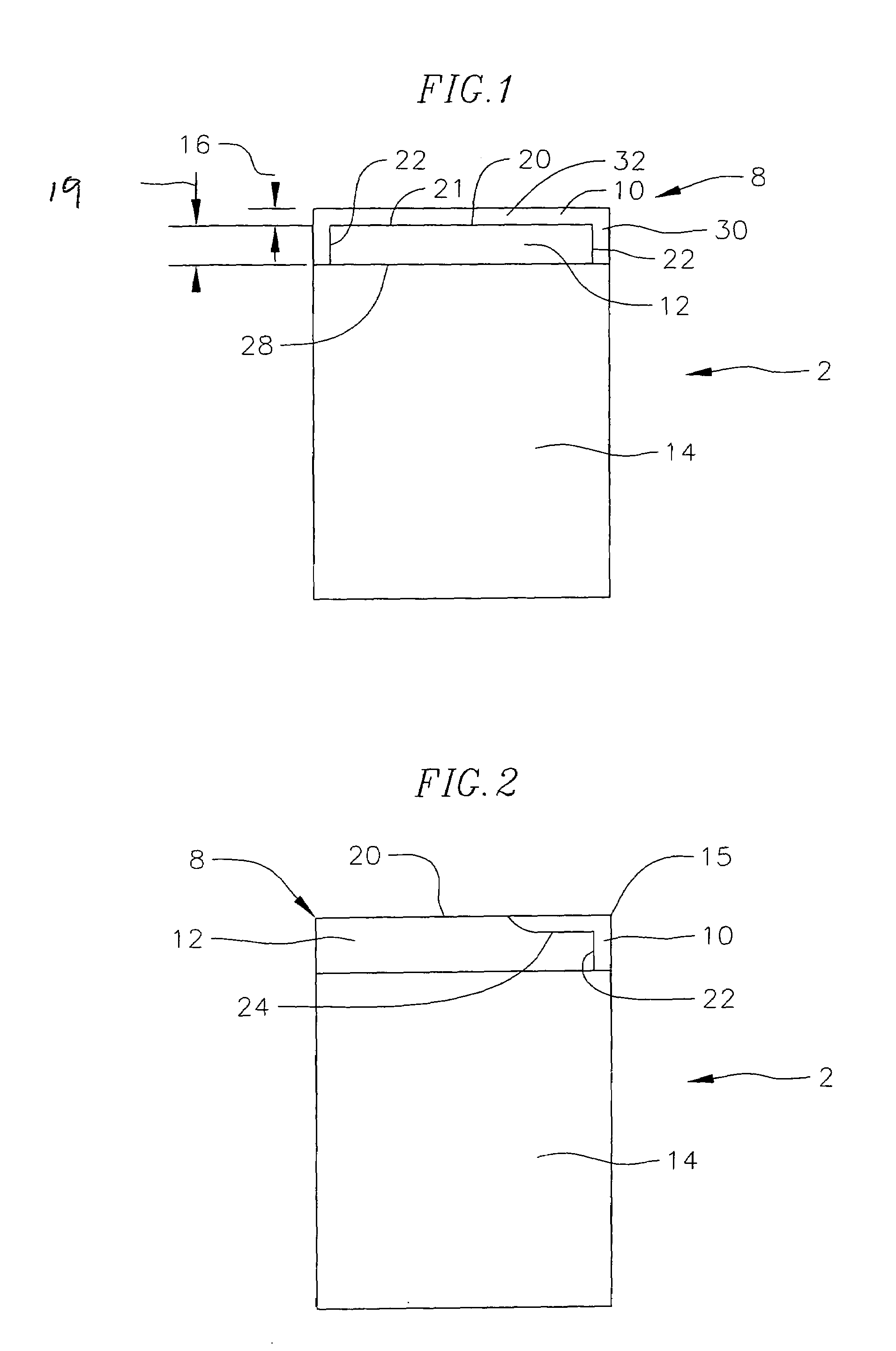
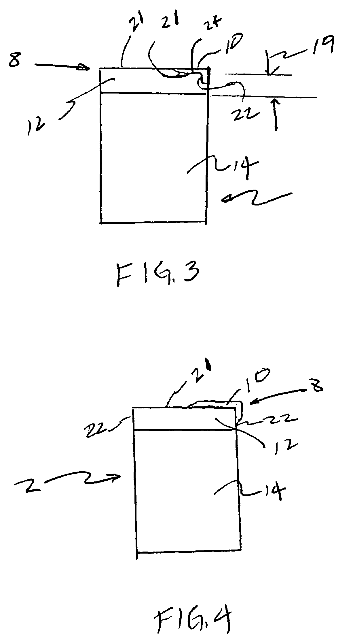
[0016]To improve the abrasion resistance, strength and fracture toughness of cutting layers of exemplary embodiment cutting elements 2 of the present invention, the inventive cutting layers 8 incorporate an outer ultra hard material layer 10 formed over an inner ultra hard material layer 12, both of which are formed over a substrate 14, as for example shown in FIG. 1. The term “substrate” as used herein means any substrate over which is formed the ultra hard material layer. For example a “substrate” as used herein may be a transition layer formed over another substrate. Moreover, the terms “upper” and “lower” as used herein are relative terms to denote the relative position between two objects and not the exact position of two objects. For example an upper object may be lower than a lower object.

[0017]In one exemplary embodiment, the outer ultra hard material layer 10 has a higher abrasion strength than the inner ultra hard material layer 12. In another exemplary embodiment, the out...


PUM

PropertyMeasurementUnit
thicknessaaaaaaaaaa
thicknessaaaaaaaaaa
thicknessaaaaaaaaaa

Abstract

Cutting elements and bits incorporating such cutting elements are provided. The cutting elements have a substrate, a first ultra hard material layer formed over the substrate, and a second ultra hard material layer formed over the first ultra hard material layer. The second ultra hard material layer has a thickness in the range of 0.05 mm to 2 mm.

Description

CROSS REFERENCE TO RELATED APPLICATION[0001]This application is based upon and claims priority on U.S. Provisional Application No. 60 / 763,624 filed on Jan. 30, 2006, the contents of which are fully incorporated herein be reference.BACKGROUND OF THE INVENTION[0002]Cutting elements used in rock bits or other cutting tools typically have a body (i.e., a substrate), which has a contact or interface face. An ultra hard material layer is bonded to the contact face of the body by a sintering process to form a cutting layer, i.e., the layer of the cutting element that is used for cutting. The substrate is generally made from tungsten carbide-cobalt (sometimes referred to simply as “cemented tungsten carbide,”“tungsten carbide”“or carbide”), while the ultra hard material layer is a polycrystalline ultra hard material, such as polycrystalline diamond (“PCD”), polycrystalline cubic boron nitride (“PCBN”) or thermally stable product (“TSP”) material such as thermally stable polycrystalline diam...

Claims


Application Information

Patent Timeline
Patent Type & Authority Patents(United States)
IPC IPC(8): E21B10/46
CPCE21B10/006E21B10/5735
Inventor EYRE, RONALD K.WILLIAMS, JOHN L.
Owner SMITH INT INC
Learn More