
Perpendicular magnetic recording medium, method of manufacturing same, and magnetic recording device

a technology of magnetic recording medium and magnetic recording layer, which is applied in the direction of data recording, instruments, coatings, etc., can solve the problems of reducing the intergranular interaction, limiting the minimization of the magnetic grains composing difficult miniaturization of the grains in the magnetic recording layer, so as to improve the resolution of the magnetic recording. , the effect of less dispersion of orientations

Active Publication Date: 2009-02-24
FUJI ELECTRIC CO LTD
View PDF12 Cites 12 Cited by
  • Summary
  • Abstract
  • Description
  • Claims
  • Application Information

AI Technical Summary

Benefits of technology

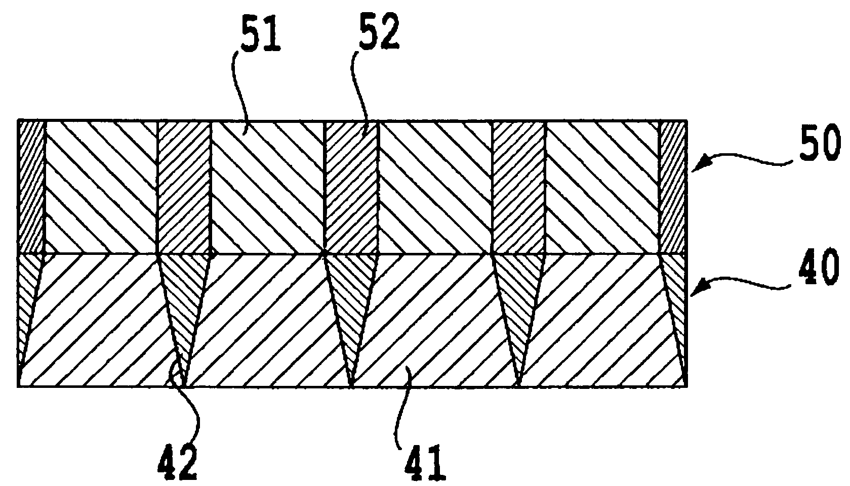
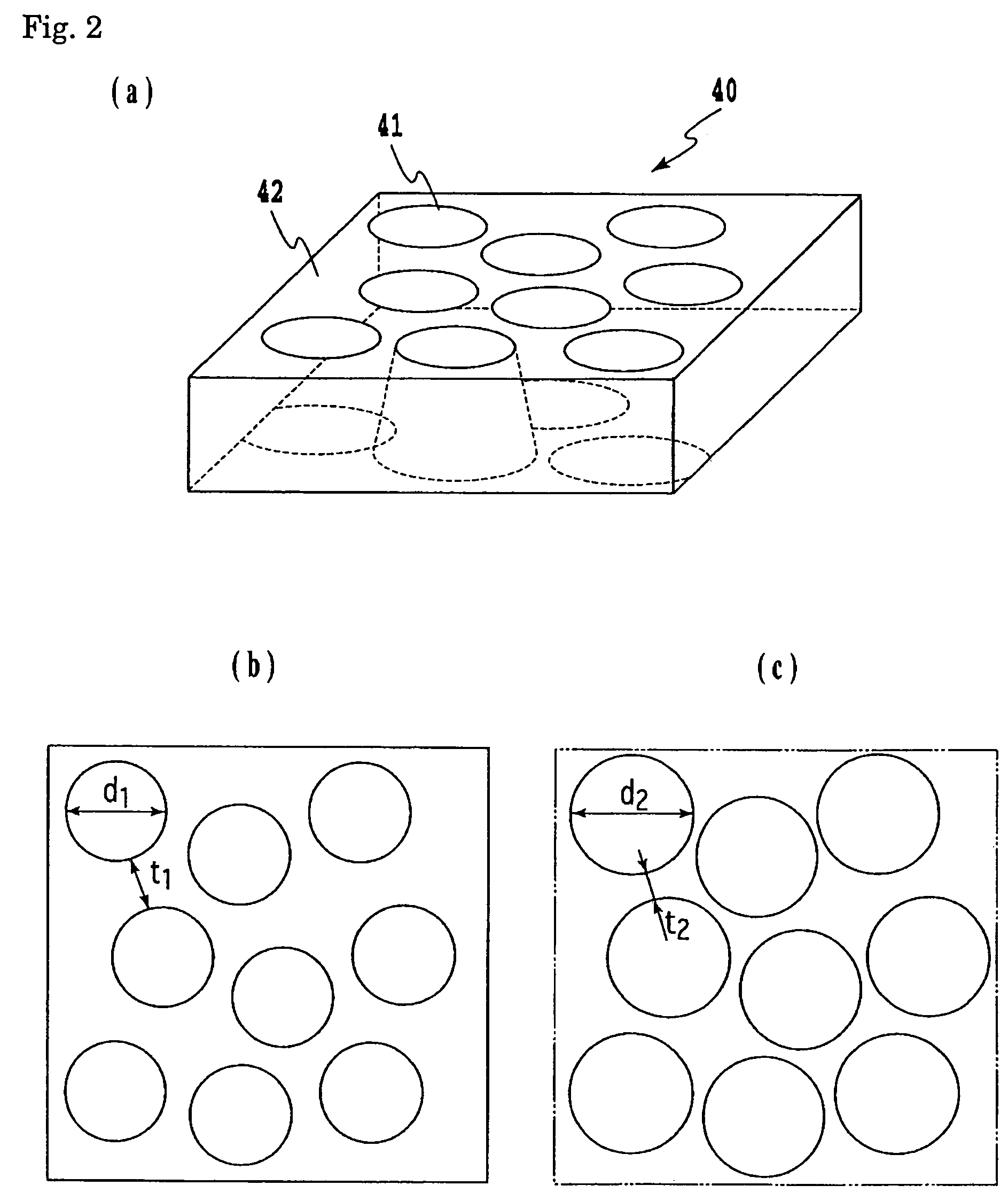
The present invention provides a perpendicular magnetic recording medium with improved resolution and high recording density. The medium comprises a perpendicular magnetic recording layer with smaller magnetic cluster sizes and reduced dispersion of orientations. The underlayer, consisting of crystal grains with a shape that reduces the grain size and the grain diameter at the bottom region, enhances the crystallinity and perpendicular magnetic anisotropy of the magnetic recording layer. The method of manufacturing the medium includes sequentially laminating an underlayer and a magnetic recording layer on a nonmagnetic substrate. The crystal grains in the underlayer have a shape that reduces the grain size and the grain diameter at the bottom region, resulting in a more favorable segregation structure and reduced media noises. The bottom region has a larger grain diameter and a smaller width of grain boundary, improving the crystallinity and resistance to thermal fluctuation of the magnetic recording layer. The underlayer can be made thinner, improving the recording capability. The flatness of the crystalline top region reduces dispersion of orientations of perpendicular magnetic anisotropy in the magnetic recording layer, reducing transition noises and increasing the perpendicular magnetization component, to enhance output signals. The shape of a truncated cone or a truncated pyramid suppresses joining of neighboring grains in the growth process, providing uniform grain diameters and reducing dispersion of grain diameters.

Problems solved by technology

However, a limitation is imposed on the minimization of the magnetic grains composing the magnetic recording layer because the magnetic grains are transformed to a superparamagnetic state and lose ferromagnetic property when the grain diameter becomes smaller than 4 nm.
Accordingly, the reduction of the intergranular interaction is a key issue for the enhancement of recording density.
The miniaturization of the grains in a magnetic layer was difficult in this type of magnetic layer material.
The method is, however, very complicated in the manufacturing process, and thus unsuitable for mass production.
The use of an underlayer having an irregular surface produced by crystal grains as proposed in Japanese Unexamined Patent Application Publication No. 2003-223712, also has a problem.
Because the number and size of the magnetic grains in the magnetic recording layer reflect the number and size of the crystal grains in the underlayer, a problem of thermal fluctuation becomes significant due to decrease of the number of magnetic grains.
As a result, grains smaller than 4 nm, which are transformed to a superparamagnetic state, increase and this also raises the problem of thermal fluctuation.
(1) to increase the number of magnetic grains per unit area,
(2) to suppress generation of superparamagnetic grains, and
(3) to reduce the dispersion of orientations in the magnetic recording layer.
Further, when the crystal grains in the underlayer is minimized for the purpose of minimization of the magnetic grains, improvement in crystallinity of the underlayer is difficult since the volume of a crystalline portion is small particularly at the initial stage of growth, which is essential to obtain the crystallinity.
For the above-described reason, it is difficult to improve medium performance or enhance recording density by using an underlayer comprising crystal grains having the shape of a sphere or an ellipsoid.
Accordingly, there remains a severe problem to obtain a method of manufacturing such a perpendicular medium that an isolation structure of an underlayer can be formed using a simple method as in a conventional manufacturing process of a medium of continuous films and the isolation structure of underlayer allows suppressing the dispersion of alignment and reducing a magnetic cluster size in a magnetic recording layer, and that a high recording density can be achieved owing to thin film thickness of the underlayer.

Method used


Image

  • Perpendicular magnetic recording medium, method of manufacturing same, and magnetic recording device
  • Perpendicular magnetic recording medium, method of manufacturing same, and magnetic recording device
  • Perpendicular magnetic recording medium, method of manufacturing same, and magnetic recording device

Examples


example 1

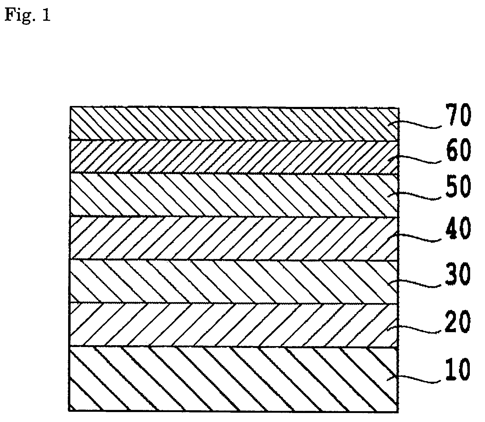
[0060]In this example, a double layer perpendicular medium having a structure as shown in FIG. 1 was manufactured. Nonmagnetic substrate 10 was a chemically strengthened glass substrate having a smooth surface (for example, N-5 glass substrate manufactured by HOYA Corporation). After cleaning, the substrate was introduced into a DC magnetron sputtering apparatus, and soft magnetic backing layer 20 of amorphous CoZrNb having a thickness of 150 nm was formed using a target of Co91Zr5Nb4 in an argon atmosphere at 5 mTorr (0.67 Pa). Then, seed layer 30 of soft magnetic NiFeSi having a thickness of 10 nm was formed using a target of Ni84Fe13Si3 in an argon atmosphere at 30 mTorr (4.0 Pa).

[0061]Next, underlayer 40 of RuSi having a thickness of 10 nm was deposited using a target of Ru95Si5 under a pressure of 30 mTorr (4.0 Pa). An atmosphere in the DC magnetron sputtering apparatus was wholly argon gas at the start of the deposition. After start of the deposition, the addition of nitrogen ...

example 2

[0063]A double layer perpendicular medium was obtained in the same manner as in Example 1 except that underlayer 40 was formed in the following way. Underlayer 40 of RuSi 10 nm thick was deposited using a target of Ru95Si5 in an argon atmosphere at 30 mTorr (4.0 Pa). After the start of deposition, the input power in the sputtering process was varied as shown in FIG. 5. The atmospheric gas in the apparatus was wholly argon gas throughout the deposition step.

example 3

[0064]A double layer perpendicular medium was obtained in the same manner as in Example 1 except that underlayer 40 was formed in the following way. Underlayer 40 of RuSi 10 nm thick was deposited using a target of Ru95Si5 in an argon atmosphere at 30 mTorr (4.0 Pa). After the start of deposition, the applied voltage to the substrate was varied as shown in FIG. 6. The atmospheric gas in the apparatus was wholly argon gas throughout the deposition step.


PUM

PropertyMeasurementUnit
grain diameteraaaaaaaaaa

Abstract

A perpendicular medium is disclosed in which an isolation structure of an underlayer is formed using a simple method as in a conventional manufacturing process for a medium of continuous films. The method suppresses dispersion of alignment and reduced magnetic cluster size in a magnetic recording layer. The perpendicular medium exhibits high recording density owing to thin film thickness of the underlayer. A perpendicular magnetic recording medium includes at least an underlayer and a magnetic recording layer sequentially laminated on a nonmagnetic substrate. The underlayer consists of crystal grains and an amorphous grain boundary, and the crystal grain has a shape holding a relation (an area of a bottom region at an initial stage of growth)>(an area of a top region).

Description

CROSS REFERENCE TO RELATED APPLICATIONS[0001]This application is based on, and claims priority to, Japanese Application No. 2004-201115, filed on Jul. 7, 2004, the contents of which are incorporated herein by reference.BACKGROUND OF THE INVENTION[0002]A. Field of the Invention[0003]The present invention relates to a perpendicular magnetic recording medium mounted on various magnetic recording devices, to a method of manufacturing the same, and to a magnetic recording device using the perpendicular magnetic recording medium.[0004]B. Description of the Related Art[0005]A perpendicular magnetic recording system in which the recording magnetization is recorded in a direction perpendicular to the plane of a medium is drawing attention as a technology to attain high density of magnetic recording in place of a conventional longitudinal magnetic recording system in which the recording magnetization is recorded in a direction along the plane of a medium. A perpendicular magnetic recording me...

Claims


Application Information

Patent Timeline
Patent Type & Authority Patents(United States)
IPC IPC(8): G11B5/64B05D5/12G11B5/738
CPCG11B5/65G11B5/7325G11B5/85G11B5/7377G11B5/737G11B5/658G11B5/657
Inventor WATANABE, SADAYUKISAKAI, YASUSHI
Owner FUJI ELECTRIC CO LTD
Learn More