
Manually-actuated metering pump

a metering pump and manual actuation technology, applied in the direction of piston pumps, positive displacement liquid engines, instruments, etc., can solve the problems of increasing the manufacturing cost and the risk of fluid returning into the bottl

Active Publication Date: 2009-01-27
LABLABO SRL
View PDF18 Cites 14 Cited by
  • Summary
  • Abstract
  • Description
  • Claims
  • Application Information

AI Technical Summary

Benefits of technology

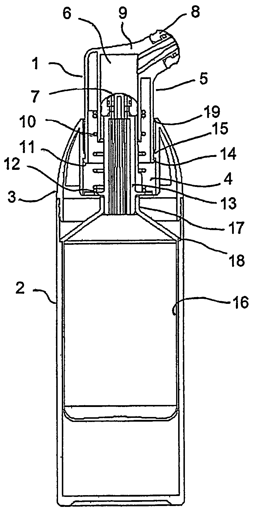
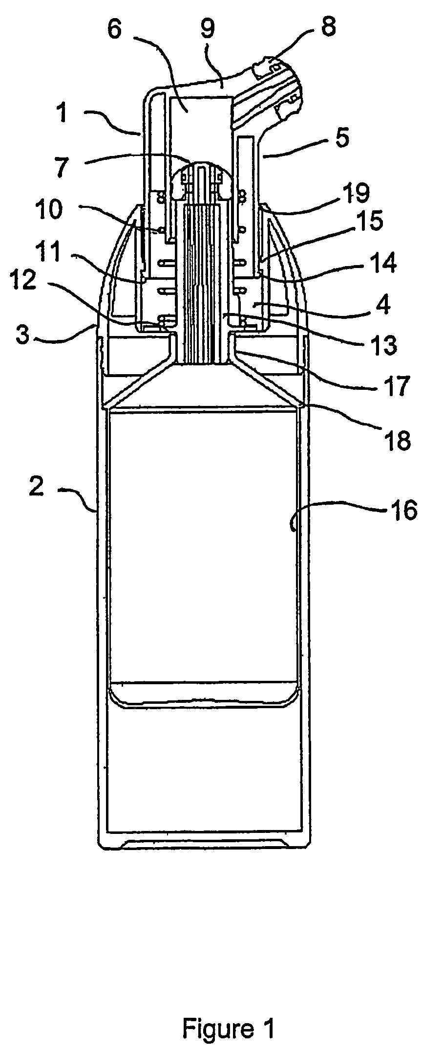
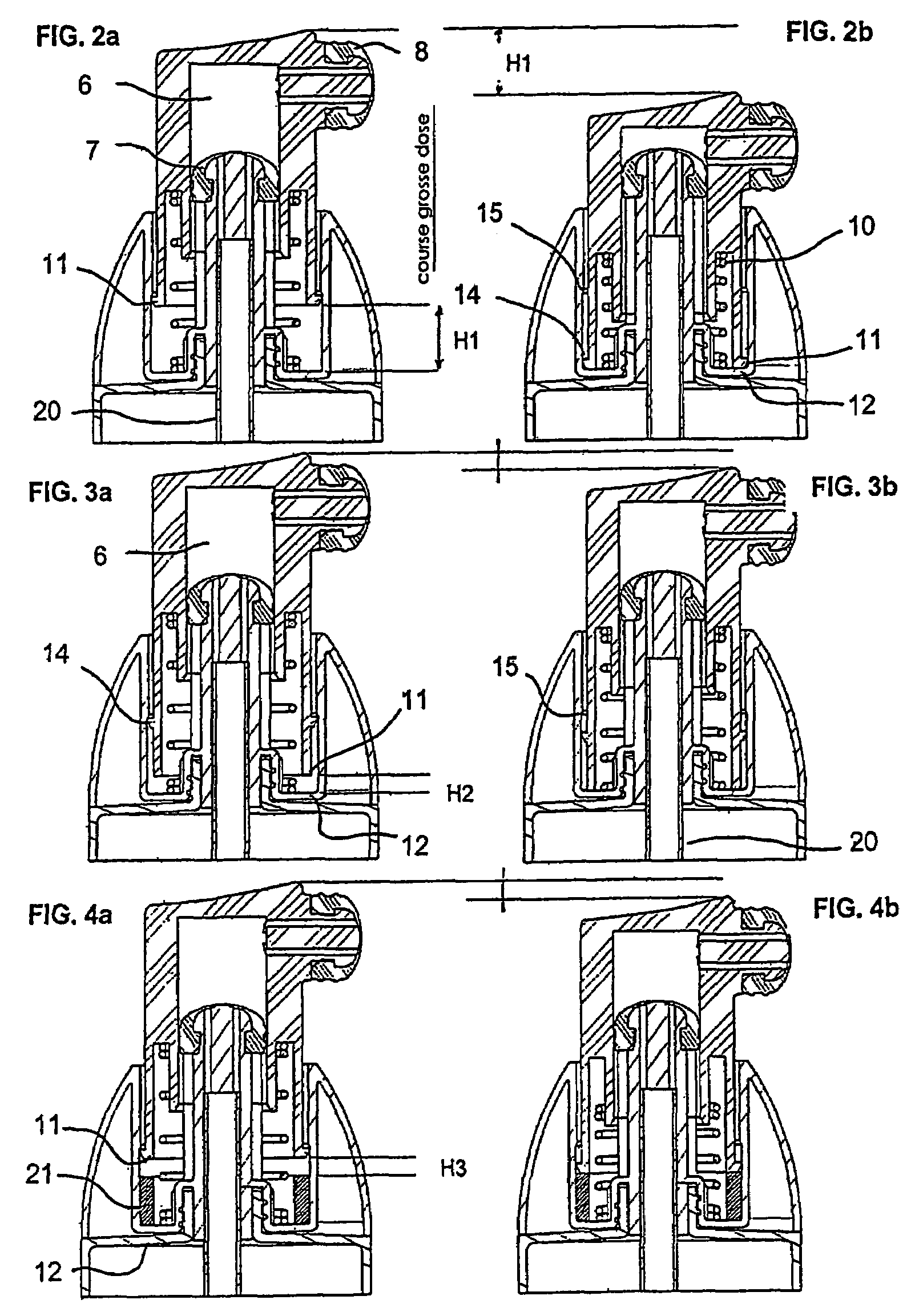
[0023]According to a preferred embodiment of the invention, the lower valve is fixed to a hollow tube that communicates with the pouch, while the upper valve is mounted on the end of the outlet nozzle of the pump. This embodiment has the advantage of constituting an outermost closure that completely eliminates the product dead volume at the outlet of the pusher, thereby making it easier to preserve said product and avoid any unsightly accumulation of product at the outlet of the pusher which could, by drying out, block the output nozzle.
[0024]The lower valve, on which the pump chamber slides, acts as a piston, thereby simplifying the manufacture of the pump.
[0025]According to another preferred feature of the invention, the two valves, namely the lower and upper valves, are identical and interchangeable when mounting the device, which considerably simplifies its manufacture and greatly reduces its cost.
[0026]According to one simple and inexpensive embodiment, the valves are formed by a cylindrical cover made of an elastic material pierced at its center and fixed to a cylindrical part forming a support and comprising an annular orifice surrounding, at its center, an element facing the hole in the cover and masking the latter. At rest, the front wall of the cover covers the annular orifice and bears on the central element. Thus, the valve is closed. An external overpressure presses the wall of the cover against its support and therefore keeps the valve closed. In contrast, an internal overpressure causes the elastic blade of the front wall of the cover to rise, exposing the annular orifice and causing the valve to open.
[0029]According to one advantageous embodiment of the present invention, the valves are made of a material having a Shore A hardness of between 40 and 80, preferably between 50 and 60.
[0030]According to the invention, it may be advantageous to mount the pump sealably on the rigid bottle via a ring or a cap. According to a variant, the pump is mounted directly on the bottle, for example by snap-fitting.
[0038]Means may be provided for ensuring that a seal is formed by the fitting arrangement between the cover and the head, for example the cover may be put into place by snap-fitting it thanks to shape complementarity between the internal edge of the cover and the base of the pusher nose receiving it, this fitting arrangement being supplemented with an O-ring seal or with sealing beads.
[0039]Such an accessory supplementing the pump and its pusher ensures that there is excellent sealing under all storage conditions, even when the external pressure drops, and allows the product contained in the bottle to be preserved.
[0045]It may be advantageous to produce the pouch from a material matched to the product that it contains. Thus, as an example, the pouch may be made of low-density polyethylene when it has to contain a cream insensitive to the effects of the external environment, whereas it may be made of a polyamide, providing better protection against the effects of oxygen and against the loss of water vapor by evaporation when it has to contain a more delicate product.

Problems solved by technology

However, pumps of this type have the drawback of comprising a relatively large number of components, which weakens them and increases their manufacturing cost.
Patent EP 0 538 162 discloses a closure device for a bottle, one variant of which includes a hollow pusher forming a metering chamber, between an output valve and an intake valve; when the pusher is actuated, the base of the part forming the lower valve is pushed back and deforms, therefore making it easier for the truncated cone surrounding the axial cylindrical part to open, which runs the risk of causing fluid to return into the bottle.

Method used


Image

  • Manually-actuated metering pump
  • Manually-actuated metering pump
  • Manually-actuated metering pump

Examples


Embodiment Construction

[0023]According to a preferred embodiment of the invention, the lower valve is fixed to a hollow tube that communicates with the pouch, while the upper valve is mounted on the end of the outlet nozzle of the pump. This embodiment has the advantage of constituting an outermost closure that completely eliminates the product dead volume at the outlet of the pusher, thereby making it easier to preserve said product and avoid any unsightly accumulation of product at the outlet of the pusher which could, by drying out, block the output nozzle.

[0024]The lower valve, on which the pump chamber slides, acts as a piston, thereby simplifying the manufacture of the pump.

[0025]According to another preferred feature of the invention, the two valves, namely the lower and upper valves, are identical and interchangeable when mounting the device, which considerably simplifies its manufacture and greatly reduces its cost.

[0026]According to one simple and inexpensive embodiment, the valves are formed by...


PUM


Abstract

The invention relates to a manually-actuated metering pump of simple design, which is intended for a rigid container. The inventive metering pump is of the dual valve type, comprising a lower inlet valve and an upper ejection valve which are disposed at the input and output respectively of a metering chamber which is slidably mounted on the lower valve. Moreover, said lower valve is fixed to a hollow tube which communicates with the inside of the container. The invention can be used for dispensing fluid products.

Description

CROSS-REFERENCE TO RELATED APPLICATIONS[0001]This application is a §371 application of International Patent Application No. PCT / FR2003 / 003725, filed Nov. 15, 2003, and published in French on Jul. 1, 2004, as International Publication No. WO 2004 / 054721 A1, which claims priority to French Patent Application No. 02 / 15854, filed Dec. 13, 2002. The disclosures of these applications are incorporated herein in their entirety.BACKGROUND OF THE INVENTION[0002]1. Field of the Invention[0003]The present invention relates to a metering pump for dispensing fluid, liquid or pasty products, and more particularly to a manually actuated metering pump for a rigid bottle having a flexible pouch or a piston and dip tube, containing a fluid, liquid or pasty product intended to be delivered in constant individual doses, and to a dispensing device equipped with such a pump.[0004]2. Description of the Related Art[0005]The operating principle of metering pumps for dispensing fluid, liquid or pasty products...

Claims


Application Information

Patent Timeline
Patent Type & Authority Patents(United States)
IPC IPC(8): B65D88/54B05B11/00
CPCB05B11/0018B05B11/0021B05B11/0024B05B11/0072B05B11/3004B05B11/3074B05B11/0016B05B11/0043B05B11/0044B05B11/00444B05B11/00446B05B11/00442B05B11/1004B05B11/026B05B11/1074B05B11/02F04B9/14B05B11/0039
Inventor ARGHYRIS, LAURENTPUVILAND, PATRICETABERLET, JEAN-PHILIPPE
Owner LABLABO SRL
Learn More