
Device and method for generating extreme ultraviolet (EUV) radiation

a technology of ultraviolet radiation and collector optics, applied in the direction of optical radiation measurement, instruments, therapy, etc., can solve the problems of reducing the overall efficiency of the collector optics, reducing the overall efficiency of the power achieved at the intermediate focus of the applied electrical input power for the discharge, and the collector optics used for bundling and deflecting euv radiation are subject to increased contamination. , to achieve the effect of reducing the life of the collector optics and the electrode system, reducing

Inactive Publication Date: 2009-01-13
USHIO DENKI KK
View PDF16 Cites 14 Cited by
  • Summary
  • Abstract
  • Description
  • Claims
  • Application Information

AI Technical Summary

Benefits of technology

The invention is about a device and method for generating extreme ultraviolet (EUV) radiation by using a laser to vaporize a source material for the electric discharge. The vaporized material is then introduced into a discharge area and vaporized there, resulting in a higher conversion efficiency of the radiation output. The device can include a gas supply unit and a thinning device to remove excess individual volumes. The method can involve directing laser beam pulses or a background gas flow through the discharge area to vaporize the source material. The invention aims to optimize the conversion efficiency of the device without reducing the life of the collector optics and electrode system.

Problems solved by technology

The problems to be solved stem in part from the dilemma that increasing the distance between the plasma and electrodes, which has a positive effect on the life of the electrodes, leads to reduced efficiency of the collector optics because of the resulting increase in generated plasma, so that there is a reduction in overall efficiency with respect to the power achieved at the intermediate focus for the applied electrical input power for the discharge.
Tin and lithium have the substantial disadvantage of a high level of debris, so that the collector optics used for bundling and deflecting the EUV radiation are subject to increased contamination.

Method used


Image

  • Device and method for generating extreme ultraviolet (EUV) radiation
  • Device and method for generating extreme ultraviolet (EUV) radiation
  • Device and method for generating extreme ultraviolet (EUV) radiation

Examples


Embodiment Construction

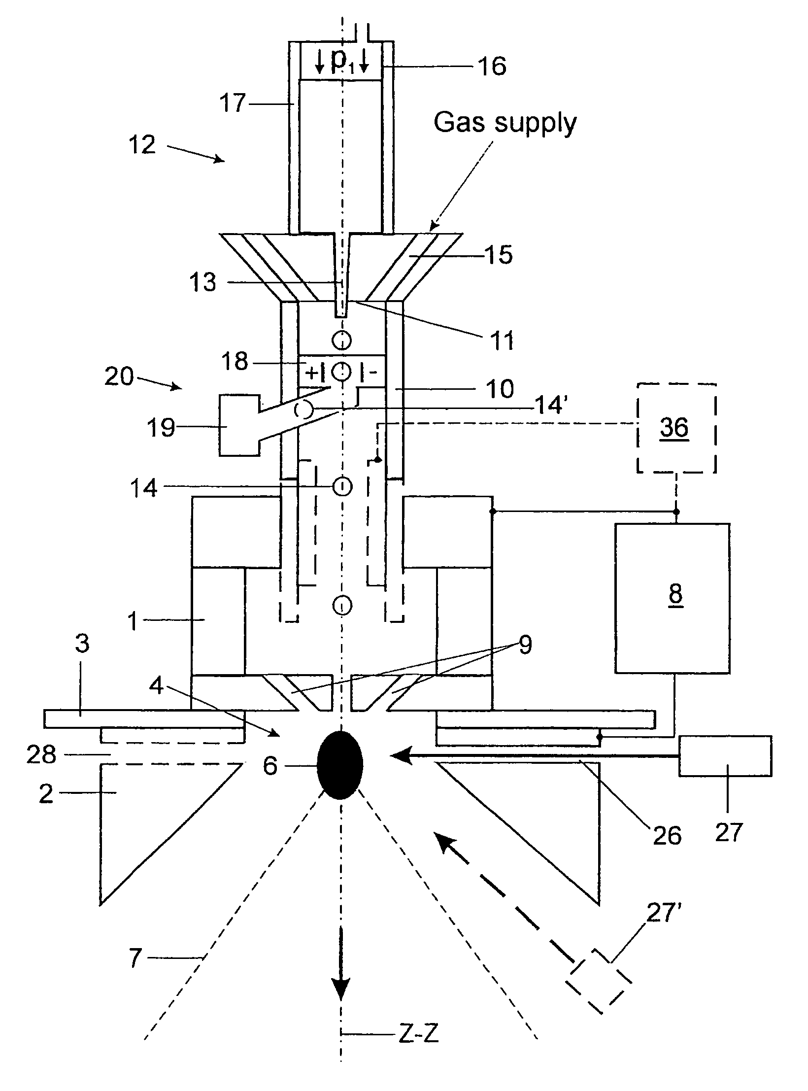
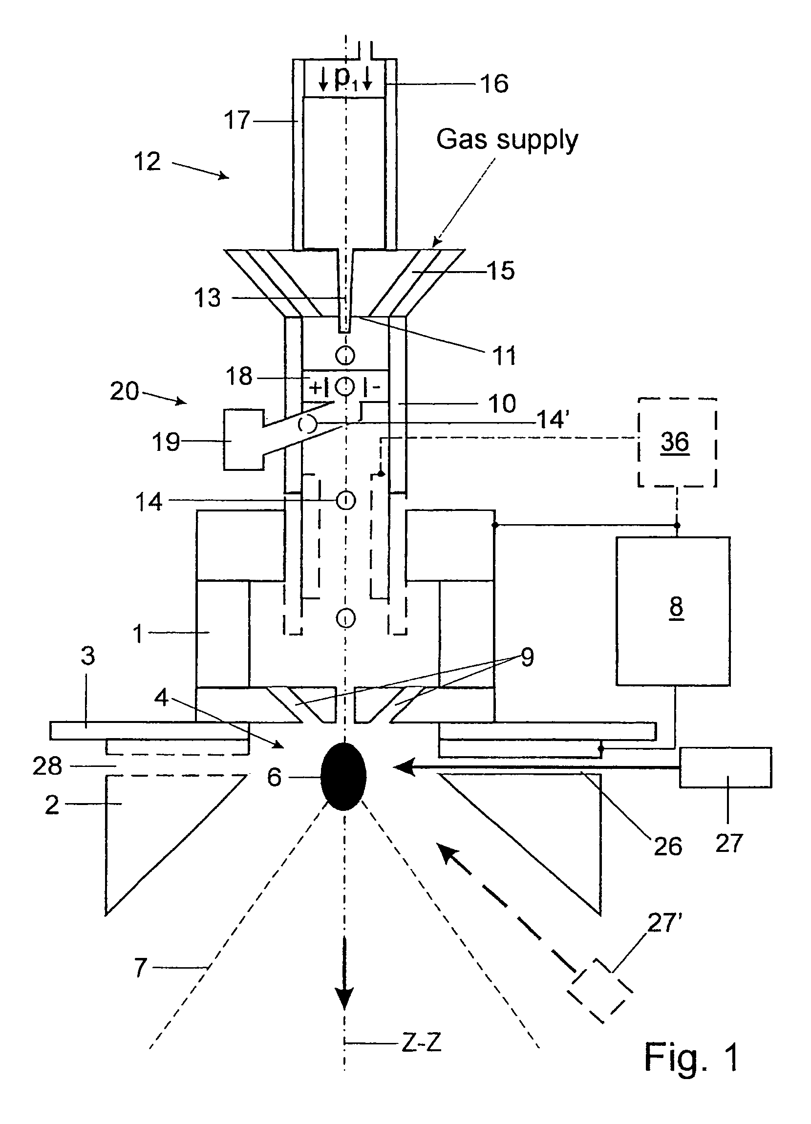
[0037]The EUV radiation source shown in FIG. 1 contains a first electrode 1 and a second electrode 2 which are separated from one another electrically by an insulator 3 with dielectric rigidity. A discharge chamber 4 contains a discharge area for a pulsed gas discharge for forming a dense, hot plasma 6 which emits the radiation. The radiation 7 emitted by the plasma 6 can exit from the EUV radiation source through the second electrode 2 which is open toward one side.

[0038]By generating high-voltage pulses with a repetition rate between 1 Hz and 20 kHz and with a pulse size sufficient for this purpose, a high-voltage pulse generator 8 connected to the two electrodes 1 and 2 ensures that the plasma 6 can emit the desired EUV radiation.

[0039]In radially symmetric openings 9 incorporated in the first electrode 1, there are plasma channels which intersect in the discharge area (pinch region).

[0040]An inlet connection piece 10 with an inlet opening 11 through which an injection device 12 ...


PUM


Abstract

It is the object of a device and method for generating extreme ultraviolet (EUV) radiation to overcome the obstacles formerly posed by the use of efficient metal emitters so that the conversion efficiency can be optimized and, as a result, the radiation output can be increased without shortening the useful life of the collector optics and electrode system. An injection nozzle of an injection device is directed to a discharge area located in a discharge chamber. The injection nozzle supplies a series of individual volumes of a source materials for the electric discharge serving to generate radiation at a repetition rate that corresponds to the frequency of the gas discharge. Further, provision is made for successively vaporizing the individual volumes in the discharge area.

Description

CROSS-REFERENCE TO RELATED APPLICATION[0001]This application claims priority of German Application No. 10 2005 007 884.2, filed Feb. 15, 2005, the complete disclosure of which is hereby incorporated by reference.BACKGROUND OF THE INVENTION[0002]a) Field of the Invention[0003]The invention is directed to a device for generating extreme ultraviolet (EUV) radiation. The device contains a discharge chamber which has a discharge area for a gas discharge in order to form a plasma that emits the radiation, a first electrode and a second electrode which are electrically separated from one another by an insulator with dielectric rigidity, an outlet opening which is provided in the second electrode for the radiation emitted by the plasma, and a high-voltage power supply for generating high-voltage pulses for the two electrodes.[0004]Further, the invention is directed to a method for generating extreme ultraviolet (EUV) radiation in which a plasma emitting the radiation is generated in a disch...

Claims


Application Information

Patent Timeline
Patent Type & Authority Patents(United States)
IPC IPC(8): H05H1/04
CPCH05G2/003H05G2/005
Inventor GAEBEL, KAIKLEINSCHMIDT, JUERGEN
Owner USHIO DENKI KK
Learn More