Method for controlling fuel injection and a motor vehicle

a technology for controlling fuel injection and motor vehicles, which is applied in the direction of electric control, engine starters, machines/engines, etc., can solve the problems of comparatively rapid pressure buildup in the accumulator volume (rail), and achieve the effect of reducing the precious metal content of the catalytic converter of the exhaust system and low emissions

Active Publication Date: 2009-01-13
VOLKSWAGEN AG +1
View PDF9 Cites 0 Cited by
  • Summary
  • Abstract
  • Description
  • Claims
  • Application Information

AI Technical Summary

Benefits of technology

[0018]The electric machine implemented as a starter generator should be capable of operating without slippage, which can be achieved, in particular, by using a starter generator driven by the crankshaft. The invention can be advantageously employed in hybrid drive concepts, wherein the vehicle is preferably powered by a parallel arrangement of the internal combustion engine and the at least one electric machine.
[0019]Because the startup operation generates low emissions, a precious metal content of the catalytic converters of the exhaust system can be reduced compared to conventional systems, without exceeding permissible emission limits. Advantageously, an exhaust system with at least one catalytic converter having a total volume of at least 0.9 l per liter displacement of the internal combustion engine can have an average precious metal content of at most 3.59 g / dm3 (100 g / ft3), in particular at most 2.87 g / dm3 (80 g / ft3), preferably at most 2.15 g / dm3 (60 g / ft3). In spite of the relatively low precious metal content, an HC emission of maximally 0.01 g / mile and a NOx emission of maximally 0.02 g / mile can be maintained during the U.S. drive cycle FTP-75 covering a distance of 120,000 miles. In particular, according to the invention, a total precious metal weight for all catalytic converters is at most 3 g / l displacement of the internal combustion engine, in particular at most 2.5 g / l displacement, preferably at most 2 g / l displacement, and most preferably at most 1.5 g / l displacement.

Problems solved by technology

The high-pressure fuel pump of the injection system is hence quickly activated, which leads to a comparatively rapid pressure buildup in the accumulator volume (rail).

Method used


Image

  • Method for controlling fuel injection and a motor vehicle
  • Method for controlling fuel injection and a motor vehicle
  • Method for controlling fuel injection and a motor vehicle

Examples


Embodiment Construction

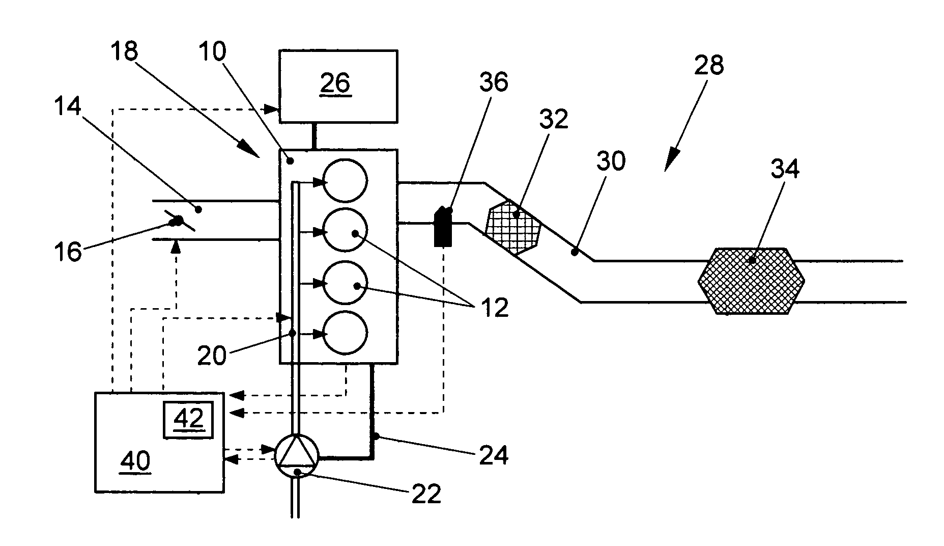
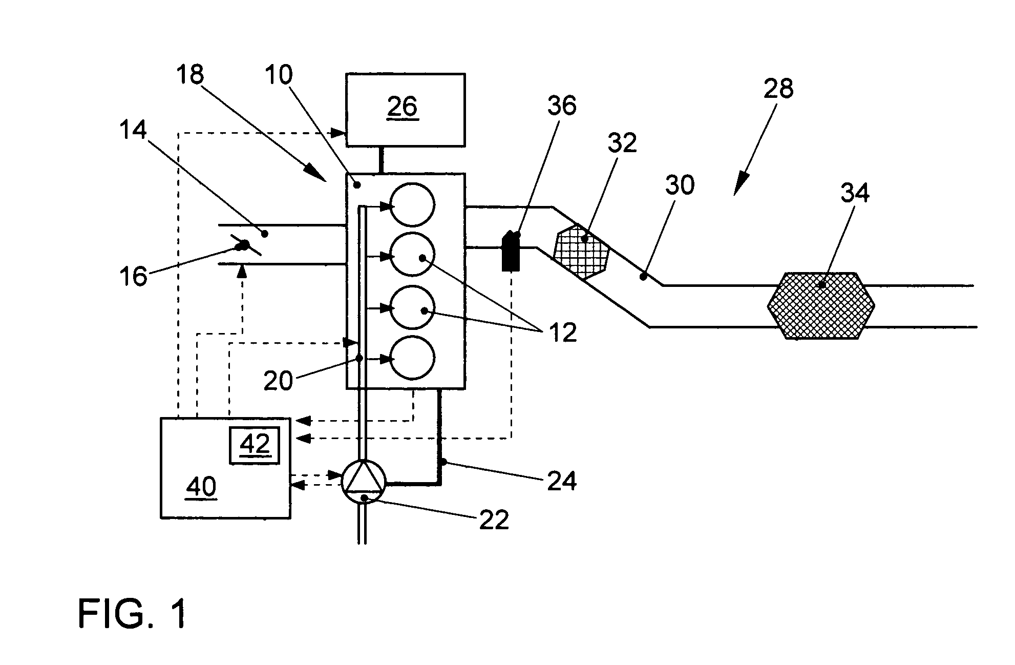
[0023]As shown in FIG. 1, the four-cycle internal combustion engine 10 capable of lean operation includes, for example, four cylinders 12. The internal combustion engine 10 can operate in a self-ignition mode (diesel engine) or can, as in the present example, operate by spark-ignition (Otto or gasoline engine). Air is supplied to the cylinders 12 through an intake manifold 14, whereby the air mass flow can be adjusted by a controllable throttle 16 as a function of the operating point. A direct injection system, shown with the reference symbol 18, is associated with the internal combustion engine 10 and injects fuel directly into the combustion chambers of cylinders 12 through fuel injection valves (injectors), which are not shown in FIG. 1. The fuel accumulates under high-pressure in a common accumulator volume 20, also referred to as a rail, which is located upstream of the injectors. The fuel pressure (rail pressure) in the accumulator volume 20 is produced by a high-pressure fuel...


PUM


Abstract

The invention is directed to a method for controlling fuel injection in an internal combustion engine (10) having at least one electric machine (26), wherein a direct injection system (18) for direct injection of fuel into at least one combustion chamber (54) of the internal combustion engine (10) is associated with the internal combustion engine (10), the direct injection system (18) including a mechanically driven high-pressure fuel pump (22) for generating a fuel pressure in an accumulator volume (20) upstream of the at least one combustion chamber (54).
It is provided that during a startup process of the internal combustion engine (10) fuel is injected by at least one of the following measures:
    • (a) activation of the fuel injection into the at least one combustion chamber (54) only after a minimum fuel pressure is reached, and
    • (b) monitoring a course of a run-up of the internal combustion engine (10) after fuel injection has begun and, if a deviation of the course from a desired course is detected, at least partial compensation of the deviation by a motor intervention of the at least one electric machine (26).
The startup process can be performed so as to result in considerable fuel savings and low emissions.

Description

FIEID OF THE INVENTION[0001]The invention relates to a method for controlling fuel injection in a startup phase of a direct-injection internal combustion engine having at least one electric engine which also operates as a starter generator, and to a motor vehicle capable of performing the method.BACKGROUND[0002]In direct-injection spark-ignition engines (Otto engines) and common rail diesel engines, fuel is typically injected directly into the combustion chamber of the cylinders by electronically controlled injection valves. The fuel is typically supplied by an electric feed pump from the fuel tank and stored at high-pressure in an accumulator volume upstream of the injection valves (injectors). The pressure in the accumulator volume is generated by a high-pressure fuel pump which is mechanically driven by the internal combustion engine, in particular by the camshaft or crankshaft. In spark-ignition engines, the typical fuel pressure in idle mode is approximately 60 bar and during n...

Claims


Application Information

Patent Timeline
Patent Type & Authority Patents(United States)
IPC IPC(8): F01N3/00
CPCF02D41/062F02D41/3863F02N11/04F02N11/0859F02D2200/0602F02N11/0814F02N11/0866
Inventor POTT, EKKEHARDHOLZ, MATTHIASZILLMER, MICHAELPROCHAZKA, DAVID
Owner VOLKSWAGEN AG
Why Eureka
Try Eureka