
Production method of polycrystalline ceramic body

a production method and technology of polycrystalline ceramics, applied in the direction of electrical equipment, basic electric elements, domestic applications, etc., can solve the problems of imposing a large environmental load, poor piezoelectric properties, and unsatisfactory piezoelectric properties, etc., to achieve excellent density, excellent density, and excellent density

Inactive Publication Date: 2008-12-30
DENSO CORP
View PDF18 Cites 22 Cited by
  • Summary
  • Abstract
  • Description
  • Claims
  • Application Information

AI Technical Summary

Benefits of technology

This method effectively produces polycrystalline ceramic bodies with enhanced density and improved piezoelectric and dielectric properties by ensuring uniform sintering and reducing voids, thereby increasing the strength and performance of the ceramic.

Problems solved by technology

However, this piezoelectric ceramic contains lead oxide (PbO) having a high vapor pressure and disadvantageously imposes a large load on the environment.
However, these lead-free piezoelectric ceramics have a problem that the piezoelectric properties are inferior to those of PZT.
However, these lead-free piezoelectric ceramics have a problem that the piezoelectric properties are not yet satisfactory as compared with the PZT-type piezoelectric ceramic.
However, in the case of producing a polycrystalline ceramic body (crystal-oriented ceramic) by sintering a plate-like powder and a raw material powder as described above, a dense polycrystalline ceramic body is disadvantageously not obtained, because the plate-like powder and the raw material powder, which are different in the particle size, are sintered.
Particularly, when a non-lead type material is used, there is a problem that voids are readily generated and densification scarcely occurs.
The polycrystalline ceramic body in which voids are generated is disadvantageous in that the piezoelectric properties such as the piezoelectric d31 constant, and the dielectric properties such as the dielectric loss, are deteriorated.
Furthermore, there is a problem that the strength decreases and the polycrystalline ceramic body is readily fractured due to fatigue or the like in the course of use.
As in the above-described technique for enhancing the crystal orientation of a ceramic, when a raw material powder prepared by blending a coarse template particle for accelerating the crystal orientation and a fine particle comprising a complementary substance for obtaining the objective ceramic is sintered, the sintering rate becomes non-uniform in the firing process due to a difference, in sinterability, between the fine particle and the coarse template particle.
For example, when the raw material powder is fired in the temperature region where sintering of the fine particle is accelerated, sintering of the coarse template particle with the fine particle can hardly proceed even though sintering of the fine particle is accelerated.
Therefore, voids are formed in the periphery of the template particle and a dense sintered body may not be obtained.
Such a problem arises not only in the case of producing a polycrystalline ceramic body comprising a crystal-oriented ceramic but also in many other cases of producing a polycrystalline ceramic body.
That is, in the case of producing a polycrystalline ceramic body by mixing and sintering raw material powders differing in the particle diameter, there is a problem that densification can hardly occur.

Method used

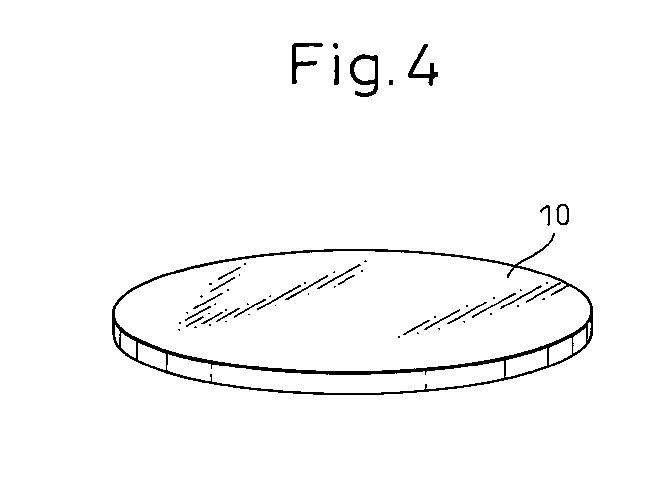

Image

  • Production method of polycrystalline ceramic body
  • Production method of polycrystalline ceramic body
  • Production method of polycrystalline ceramic body

Examples


example 1

[0227]Examples of the present invention are described below.

[0228]This Example is a case of producing a polycrystalline ceramic body.

[0229]In the production method of a polycrystalline ceramic body of this Example, a preparation step, a mixing step, a forming step and a heat-treating step are performed.

[0230]In the preparation step, a coarse particle ceramic powder having an average particle diameter of 1 to 20 μm, and a fine particle powder having an average particle diameter of ⅓ or less of the average particle diameter of the coarse particle diameter and producing a polycrystalline ceramic body when sintered with the coarse particle ceramic powder, are prepared.

[0231]In the mixing step, the coarse particle ceramic powder and the fine particle powder are mixed to produce a raw material mixture. In the forming step, the raw material mixture is formed to produce a powder compact. In the heat-treating step, the powder compact is heated, thereby shrinking the powder compact and, at th...

example 2

[0274]This Example is a case of producing a polycrystalline ceramic body having a composition different from that in Example 1. In this Example, a polycrystalline ceramic body (Sample E5) comprising a crystal-oriented ceramic with the main phase being an isotropic perovskite-type compound having a composition of formula (1) where x=0.04, y=0.54, z=0.1 and w=0.06, namely, an isotropic perovskite-type compound represented by {Li0.04(K0.46Na0.54)0.96}(Nb0.84Ta0.1Sb0.06)O3, is produced.

[0275]In the production of Sample E5, first, an anisotropically shaped powder B (BINN5) was produced in the same manner as in Example 1 and, then, the anisotropically shaped powder B was ground by dry-grinding.

[0276]Subsequently, using the anisotropically shaped powder after grinding, an anisotropically shaped powder A (NN powder) was produced as the coarse particle ceramic powder in the same manner as in Example 1. This is designated as Powder Sample A2.

[0277]Powder Sample A2 was a plate-like powder havi...

example 3

[0308]This Example is a case of producing a polycrystalline ceramic body having a composition different from those in Examples 1 and 2. In this Example, a polycrystalline ceramic body (Sample E8) comprising a crystal-oriented ceramic with the main phase being an isotropic perovskite-type compound having a composition of formula (1) where x=0.02, y=0.5, z=0 and w=0.06, namely, an isotropic perovskite-type compound represented by {Li0.02(K0.5Na0.5)0.98}(Nb0.94Sb0.06)O3, is produced.

[0309]In the production of Sample E8, first, a coarse particle ceramic powder (anisotropically shaped powder A; NN powder) was produced. As for this coarse particle ceramic powder, the same powder as Powder Sample A1 of Example 1 was prepared.

[0310]Then, Powder Sample A1, an NN power, a KN powder, an LS (LiSbO3) powder and an NS (NaSbO3) powder were weighed to a stoichiometric ratio of giving the objective composition {Li0.02(K0.5Na0.5)0.98}(Nb0.94Sb0.06)O3 and formed into a slurry, and the slurry was forme...


PUM

PropertyMeasurementUnit
particle diameteraaaaaaaaaa
aspect ratioaaaaaaaaaa
particle diameteraaaaaaaaaa

Abstract

To provide a production method of a polycrystalline ceramic body with excellent density, a preparation step, a mixing step, a forming step and a heat-treating step are performed. In the preparation step, a coarse particle ceramic powder, and a fine particle powder having an average particle diameter of ⅓ or less of the average particle diameter of the coarse particle ceramic powder are prepared. In the mixing step, the coarse particle ceramic powder and the fine particle powder are mixed to produce a raw material mixture. In the forming step, the raw material mixture is formed to a shaped body. In the heat-treating step, the shaped body is heated and thereby sintered to produce a polycrystalline ceramic body. In the heat-treating step, a temperature elevating process and a first holding process are performed and at the same time, a second holding process and / or a cooling process are performed. In the temperature elevating process, heating is started to elevate the temperature and in the first holding process, the shaped body is held at a temperature T1° C. In the second holding process, the shaped body is held at a temperature T2° C. lower than the temperature T1° C. In the cooling process, the shaped body is cooled at a temperature dropping rate of 60° C. / h or less from the temperature T1° C.

Description

TECHNICAL FIELD[0001]The present invention relates to a production method of a polycrystalline ceramic body.BACKGROUND ART[0002]A polycrystalline body comprising a ceramic (a polycrystalline ceramic body) is used, for example, in sensors for temperature, heat, gas, ions and the like, electron circuit parts such as capacitors, resistors and integrated circuit boards, and optical or magnetic recording elements. In particular, a polycrystalline ceramic body having a piezoelectric effect (hereinafter referred to as a “piezoelectric ceramic”) is being widely used in the field of electronics or mechatronics because of its high performance, high degree of freedom in shape and relatively easy material design.[0003]The piezoelectric ceramic is obtained by subjecting a ferroelectric ceramic to a so-called polarizing process of applying an electric field to align the direction of polarization of the ferroelectric material to a fixed direction. In order to align spontaneous polarization to a fi...

Claims


Application Information

Patent Timeline
Patent Type & Authority Patents(United States)
IPC IPC(8): C04B35/64C04B33/32C04B35/622C04B35/00
CPCC04B35/495C04B35/6303H01L41/43H01L41/1873C04B2235/3201C04B2235/3203C04B2235/3251C04B2235/3255C04B2235/3267C04B2235/3291C04B2235/3294C04B2235/3298C04B2235/5292C04B2235/5296C04B2235/5436C04B2235/5445C04B2235/6025C04B2235/6562C04B2235/6565C04B2235/768C04B2235/77C04B2235/787C04B2235/9615H10N30/8542H10N30/097
Inventor NAKAMURA, MASAYANAGAYA, TOSHIATSUNONOYAMA, TATSUHIKOTAKAO, HISAAKISAITO, YASUYOSHIHOMMA, TAKAHIKOTAKATORI, KAZUMASA
Owner DENSO CORP
Learn More