
Pipe joint structure and method for fabricating the same

a pipe joint and pipe joint technology, applied in the direction of branching pipes, transportation and packaging, light and heating equipment, etc., can solve the problems of inability to meet the requirements of pipe joint height, increase the cost of fabrication, and increase the height of pipe joints, etc., to suppress the cost of fabrication and reduce the joint height

Inactive Publication Date: 2008-12-30
DENSO CORP
View PDF21 Cites 18 Cited by
  • Summary
  • Abstract
  • Description
  • Claims
  • Application Information

AI Technical Summary

Benefits of technology

The present invention provides a pipe joint structure and a method for fabricating it that eliminates the need for a straight part in the pipe axis, reduces the joint height, and suppresses the fabrication costs. This is achieved by a connection flange member with a through hole and an enlarged recess, an annular protrusion press-fitted and deformed, and a non-circular shape of the enlarged recess. The non-circular shape improves the effect of preventing the pipe from rotation. The pipe and connection flange member are made of aluminum alloys, and the hardness of the alloy is higher than that of the pipe, allowing for smooth deformation during press fitting and fixing without problems. The through hole and enlarged recess can be directly opened to the exterior of the connection flange member, allowing for bending of the pipe in advance and further reduction in joint height. The connection flange member can hold multiple pipes.

Problems solved by technology

This results in the problem of an inevitable increase in the height H of the pipe joint.
Nevertheless, this conventional art requires laborious cutting, and additionally requires brazing aside from the cutting.
There has thus been the problem of a significant increase in fabrication costs.

Method used


Image

  • Pipe joint structure and method for fabricating the same
  • Pipe joint structure and method for fabricating the same
  • Pipe joint structure and method for fabricating the same

Examples


first embodiment

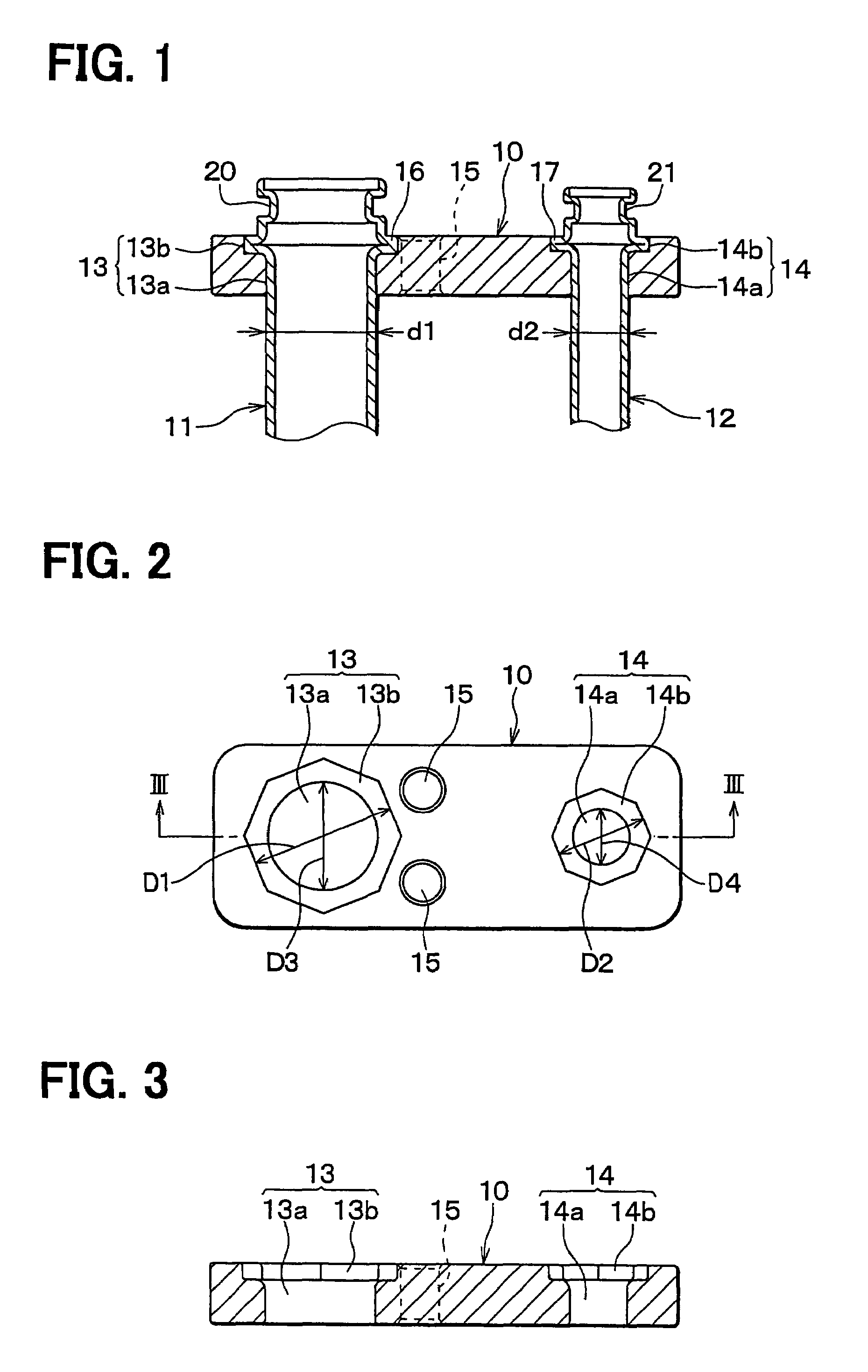
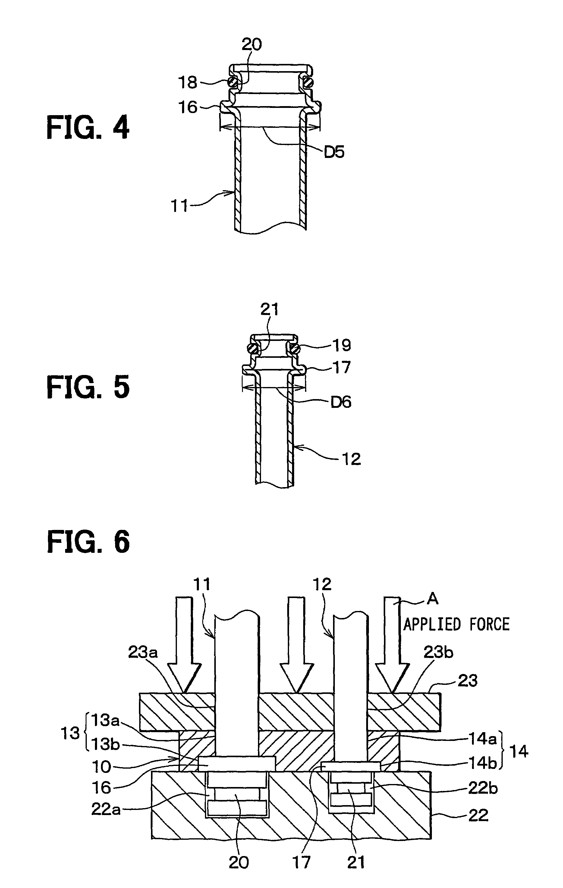
[0054]FIGS. 1 to 5 show a first embodiment. The pipe joint structure of the first embodiment illustrates one intended to connect refrigerant piping of a vehicle air conditioning refrigeration system.

[0055]A connection flange member 10 serves as a member for holding and fixing two refrigerant pipes 11, 12. The connection flange member 10 has the general shape of a rectangular plate as shown in FIGS. 2 and 3. Of the two refrigerant pipes 11, 12, one refrigerant pipe 11 having a large diameter d1 is a low-pressure refrigerant pipe of the refrigeration cycle, and more specifically a refrigerant pipe on the suction side of a compressor. The other refrigerant pipe 12 having a smaller diameter d2 is a high-pressure refrigerant pipe of the refrigeration cycle, and more specifically a high-pressure refrigerant pipe lying on the inlet side of an expansion valve.

[0056]The low-pressure (suction-side) refrigerant pipe 11 is connected at its top to the low-pressure refrigerant outlet of an expans...

second embodiment

[0078]In the first embodiment, the through holes 13, 14 in the connection flange member 10 have a circumferentially closed configuration such that they are not open to the side edges of the connection flange member 10. In a second embodiment, as shown in FIGS. 8 and 9, the through holes 13, 14 are modified into the circumferentially open configuration such that they are open to the exterior via openings 13c, 14c. FIG. 10 is an explanatory diagram showing an assembly method of the second embodiment. FIGS. 11A and 11B show the state after the assembly of the second embodiment.

[0079]Here, the direction of opening of the openings 13c, 14c is parallel to the minor-side direction B of the connection flange member 10. Through these openings 13c, 14c, the circular holes 13a, 14a and the enlarged recesses 13b, 14b of the through holes 13, 14 open partly, in terms of the circumferential direction, to a side edge 10a of the connection flange member 10 in the major-axis direction. Here, the wid...

third embodiment

[0090]The third embodiment is a modification of the first embodiment. As shown in FIGS. 12 and 13, the connection flange member 10 is provided with a single through hole 13. Only a single refrigerant pipe 11 is press-fitted and fixed to the polygonal enlarged recess 13b of the through hole 13.


PUM


Abstract

A pipe joint structure capable of reducing the joint height (H) and fabrication costs has a connection flange member provided with a through hole piercing the thickness of the flange member. A polygonal enlarged recess greater than the inner diameter of the through hole is formed at one end of the through hole. Meanwhile, an annular protrusion protruding radially outward is formed near an end of a pipe having an outer diameter capable of insertion into the through hole. This annular protrusion has an outer diameter greater than the incircle diameter of the polygonal enlarged recess. The annular protrusion is press-fitted and fixed to the polygonal enlarged recess.

Description

CROSS REFERENCE TO RELATED APPLICATION[0001]This application is based upon, claims the benefit of priority of, and incorporates by reference, the contents of Japanese Patent Application No. 2002-192203 filed Jul. 1, 2002.BACKGROUND OF THE INVENTION[0002]1. Field of the Invention[0003]The present invention relates to a pipe joint structure and a method for fabricating the same in which a pipe is provided with an annular protrusion protruding radially outward, and this annular protrusion and a through hole part in a connection flange member are press-fitted and fixed to each other. The invention is suitably applicable to a refrigerant pipe joint of a vehicle air conditioning refrigeration system, for example.[0004]2. Description of the Related Art[0005]FIG. 22 shows a conventional pipe joint structure disclosed in Japanese Patent Laid-Open Publication No. Hei 4-266521. In this conventional art, an annular protrusion 16 protruding radially outward is formed near an end of a pipe 11 by ...

Claims


Application Information

Patent Timeline
Patent Type & Authority Patents(United States)
IPC IPC(8): F16L39/00F16L19/04F16L23/024B60H1/32F16L23/026F16L23/028F16L41/08F25B41/00F28F9/04F28F9/26
CPCF16L39/00F16L41/086F28F9/0246F28F9/262F16L23/024
Inventor INABA, ATSUSHISAKAI, KOJI
Owner DENSO CORP
Learn More