Apparatus, signal-processing circuit and device for magnetic recording system
a technology of magnetic recording system and signal processing circuit, which is applied in the field of magnetic recording/reproduction apparatus, can solve the problems of deteriorating signal-to-noise ratio, high noise and distortion of medium noise in signals, etc., and achieve the effect of high-reliability data detection
- Summary
- Abstract
- Description
- Claims
- Application Information
AI Technical Summary
Benefits of technology
Problems solved by technology
Method used
Image
Examples
embodiment 1
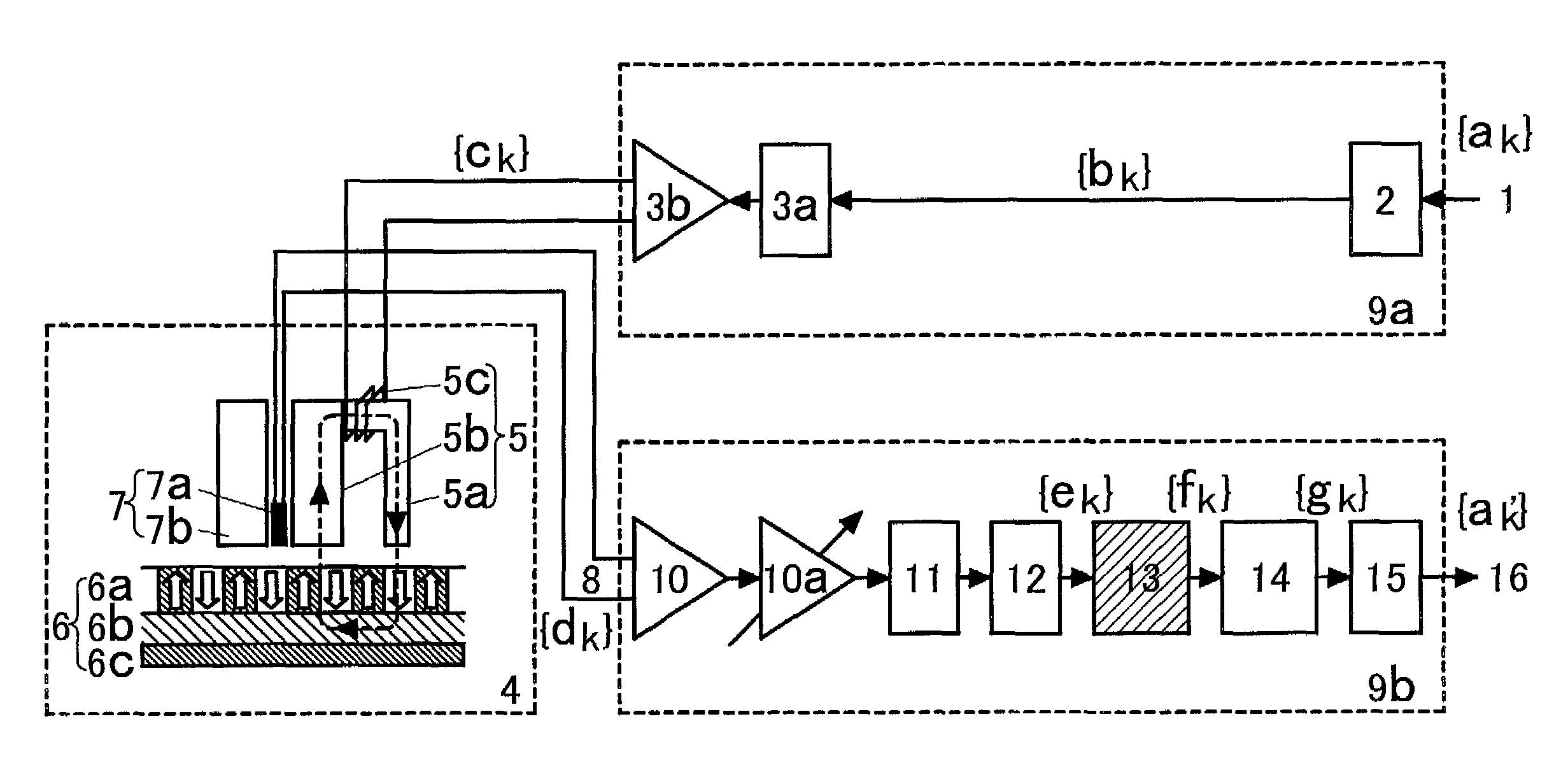
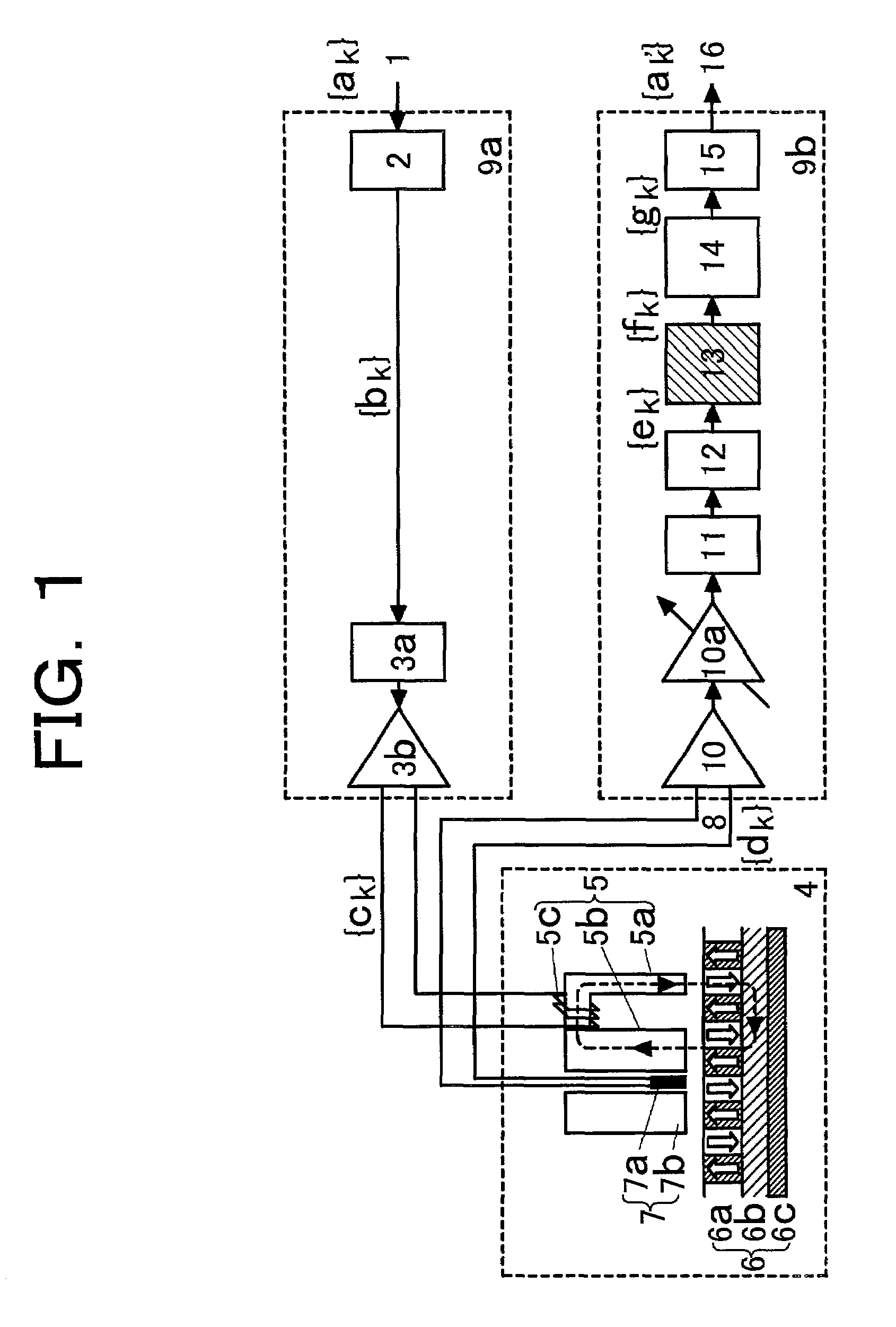
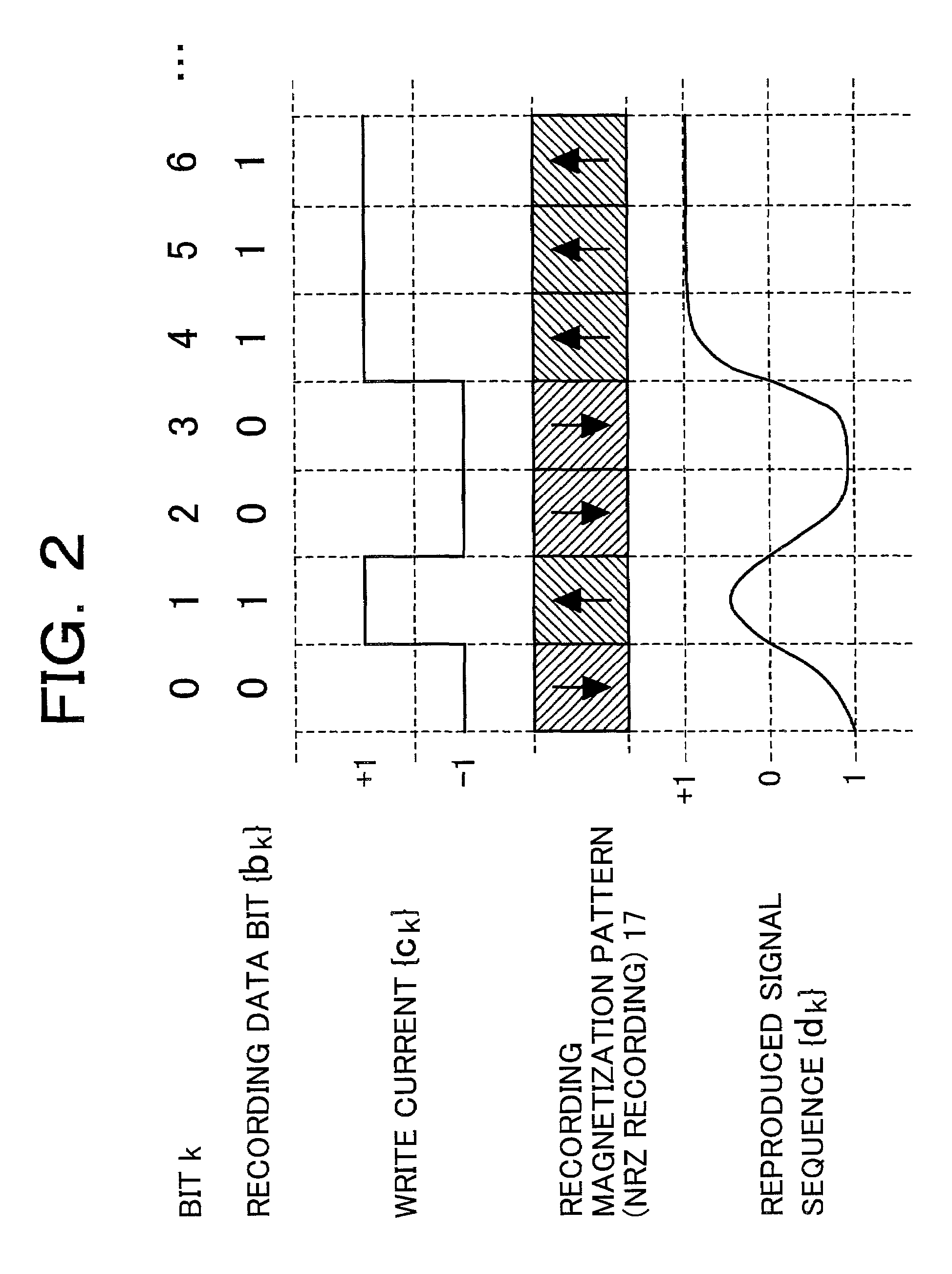
[0028]FIG. 1 is a fundamental configuration of an embodiment of a magnetic recording / reproducing apparatus according to the present invention. In the embodiment, information bit data 1 {ak} (k is an integer indicating a bit time) supplied to a recording signal processing circuit 9a is subjected to predetermined bit conversion by a coder 2 into recording bit data {bk}. The recording bit data {bk} is converted into an analog write current {ck} via a write current converting circuit 3a and a write amplifier 3b. Then, the analog write current {ck} is supplied to a perpendicular magnetic recording head medium system 4 so that information recording is performed in the perpendicular magnetic recording head medium system 4.
[0029]The perpendicular magnetic recording head medium system 4 comprises a recording head 5, a recording medium 6 and a reproducing head 7. The recording medium 6 is made of a double-layer perpendicular magnetic recording medium which has a recording magnetic layer 6a, a...
embodiment 2
[0056]In the equalizer 13 according to the present invention, the low-frequency component of the reproduced signal containing the DC component can be adjusted flexibly by changing the suppression parameter α. This flexible adjustment can help to reduce an influence of the DC component off-set or the low-frequency variation / distortion which often occurs in the real reproduced signal. Particularly, in the high-density recording / reproducing system, due to variation in characteristic of the reproducing head 7, and the shortened distance between the reproducing head 7 and the recording medium 6, there occur remarkably thermal asperity (hereinafter, abbreviated to TA) phenomena because MR characteristic is changed largely due to the temperature rising caused by the contact between the MR effect device 7a and the recording medium 6. Consequently, a DC offset variation large enough to exceed a normal maximum amplitude occurs in the reproduced signal. FIG. 12 is a typical diagram for explain...
embodiment 3
[0060]As a specific configuration for achieving a circuit which is used selectively for different equalization characteristics in accordance with the reproduced signal, there may be used a configuration in which one reproducing system signal processing circuit is formed to make equalizer parameters variable for different equalization characteristics, as shown in FIG. 13. Alternatively, there may be used another configuration, according to an embodiment shown in FIG. 14, in which a plurality of systems each constituted by equalizers 13 and a maximum-likelihood decoder 16 as a pair are prepared. The equalizers 13 have different DC low-frequency component passing characteristics from one another. On the basis of an irregular signal detected by the TA detection circuit 29 or the like, a data detection result with higher reliability can be obtained by selectively supplying the reproduced signal to one of the plurality of systems. Alternatively, when the irregular signal is detected, a da...
PUM
| Property | Measurement | Unit |
|---|---|---|
| soft | aaaaa | aaaaa |
| frequency | aaaaa | aaaaa |
| bit length | aaaaa | aaaaa |
Abstract
Description
Claims
Application Information
 - R&D
- Intellectual Property
- Life Sciences
- Materials
- Tech Scout
- Unparalleled Data Quality
- Higher Quality Content
- 60% Fewer Hallucinations
Browse by: Latest US Patents, China's latest patents, Technical Efficacy Thesaurus, Application Domain, Technology Topic, Popular Technical Reports.
© 2025 PatSnap. All rights reserved.Legal|Privacy policy|Modern Slavery Act Transparency Statement|Sitemap|About US| Contact US: help@patsnap.com


