Wastewater chemical/biological treatment plant recovery apparatus and method

a technology of chemical/biological treatment and recovery equipment, which is applied in the direction of sedimentation separation, solid separation, different sedimentation, etc., can solve the problems of unsuitable material for any beneficial use, unsuitable sludge or biosolids arising from industrial discharges, and limit the application of semi-liquid material to nearby farmland, etc., to achieve the effect of minimizing the exposure to contaminant, avoiding the impact of transportation costs, and avoiding contamination

Active Publication Date: 2008-08-26
EARTH RENAISSANCE TECH
View PDF4 Cites 42 Cited by
  • Summary
  • Abstract
  • Description
  • Claims
  • Application Information

AI Technical Summary

Benefits of technology

[0023]Next, the treatment plant's present or projected end use effluent discharge requirements for various contaminants are reviewed and compared against the water quality analysis of the contaminant and solids composition at various points within the plant or at a new plant's headworks. A treatment point is then selected for pH adjusting and injecting sulfur dioxide into the wastewater to meet all or most of the end use effluent discharge requirements. A typical wastewater treatment plant employs sequential processes, which successively concentrate solids for separation and disposal. Unfortunately, this also concentrates the dissolved salts and contaminants in the liquid fraction, causing sequentially treated liquids to often exceed the effluent limits of the plant's discharge permit. Consequently, the present method is preferably applied at points further upstream, such as the entering influent at the treatment plant head works, as the point for deodorizing and conditioning the wastewater. However, it may also be employed at any wastewater treatment point where the concentrates of the effluent salts and contaminants are not too high for land application in combination with sulfurous acid for soil conditioning and plant growth. Thus, where the attached claims refer to “inflows” or “influent”, it is also contemplated that the method and apparatus applies to the treatment of effluent and decant wastewaters where their concentrations of salts and contaminants are not too high for land application when acidified with sulfurous acid to effectuate solids conditioning and plant growth. As sulfurous acid reduces the bicarbonate buildup in soils allowing better water penetration and washing of salts out of soils, sulfurous acid treated waters, even with higher salt concentrations, still provide waters of sufficient quality for crop cultivation. Consequently, the treatment point may be selected at any point in the wastewater treatment plant where the resultant sulfurous acid treated wastewater is disinfected and produces a conditioned water suitable for land application.
[0063]The actual design of the wastewater treatment apparatus employing the method depends on the polishing requirements of the separated water for end use. The small footprint and rapid chemical treatment of the wastewater inflows provides opportunities to install the system and re-inject the treated wastewaters at various points in an existing plant. Thus, portions of an existing plant's processing equipment are often incorporated in treating the solids and separated liquids by combining treatment streams and solids. For example, where an existing plant has generated higher moisture content polymer separated solids, these may be admixed with the drier chemically separated dried solids in a ratio to provide a combined fuel with reduced overall moisture content for burning or gasification. Also, if the existing plant produces a lower BOD dissolved solid liquid stream, they may be combined with the higher acid treated BOD liquid stream to produce an overall lower dissolved solid liquid fraction requiring less biological treatment.SUMMARY

Problems solved by technology

The presence of contaminants in the sludge or biosolids arising from industrial discharges is a more challenging problem and may be the deciding factor in determining the choice of a utilization disposal option.
The contaminants accumulate in the biomass and sludge, and can render the material unfit for any beneficial use.
Primary and secondary sludge generally contain no more than four percent solids, and the storage and transportation costs of this semi-liquid material limit the application to nearby farmland.
This gelatinous mechanically separated mass is then usually land filled or admixed with other fuels for burning, and may contain significant pathogens and heavy metals.
If these separated solids are treated with chlorine for pathogen kill, chlorinated carcinogens often result, creating a different environmental hazard.
If treated with chlorine to kill pathogens before land application or dumping, its usage for agricultural purposes is lost as chlorine acts as an herbicide.
Other mechanical filtration methods provide sludge separation, but require continual unplugging of the filters; thereby generating significant ongoing costs of filter replacement and declining effectiveness as the filter is entrained with the separated solids.
As long as a mechanical sewage separation plant does not have to be moved and operates within its environmental discharge and landfill permit constraints, it provides a low operating and maintenance cost effective sewage disposal method but requires significant upfront capital investment and may result in long term environmental clean-up costs.
As urban populations being served grow, and landfill costs increase, these plants seldom meet permitting constraints without significant upgrades in design, particularly with respect to pathogen gray water discharge and the negative impacts caused by mountains of gelatinous solids.
These chemical wastewater treatment methods are not package systems, which can be moved to accommodate the needs of a community, particularly in riparian areas subject to flooding, and rely heavily on polymers.
They do not address BOD's and ammonia in treated wastewater.

Method used


Image

  • Wastewater chemical/biological treatment plant recovery apparatus and method
  • Wastewater chemical/biological treatment plant recovery apparatus and method
  • Wastewater chemical/biological treatment plant recovery apparatus and method

Examples


Embodiment Construction

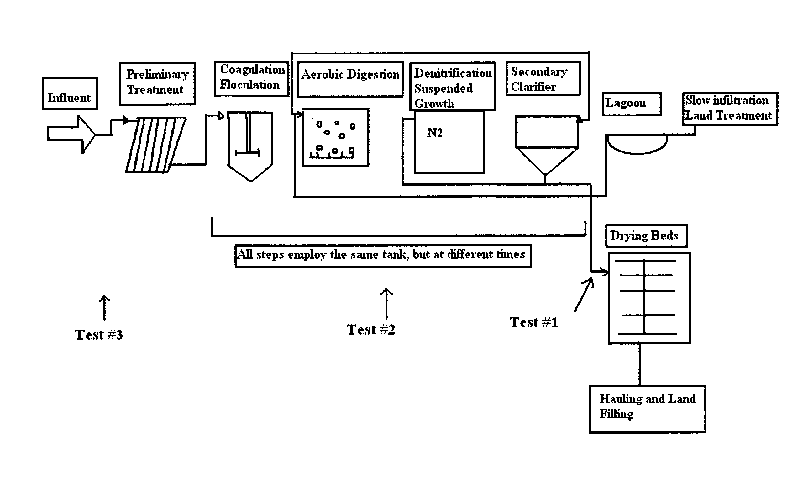
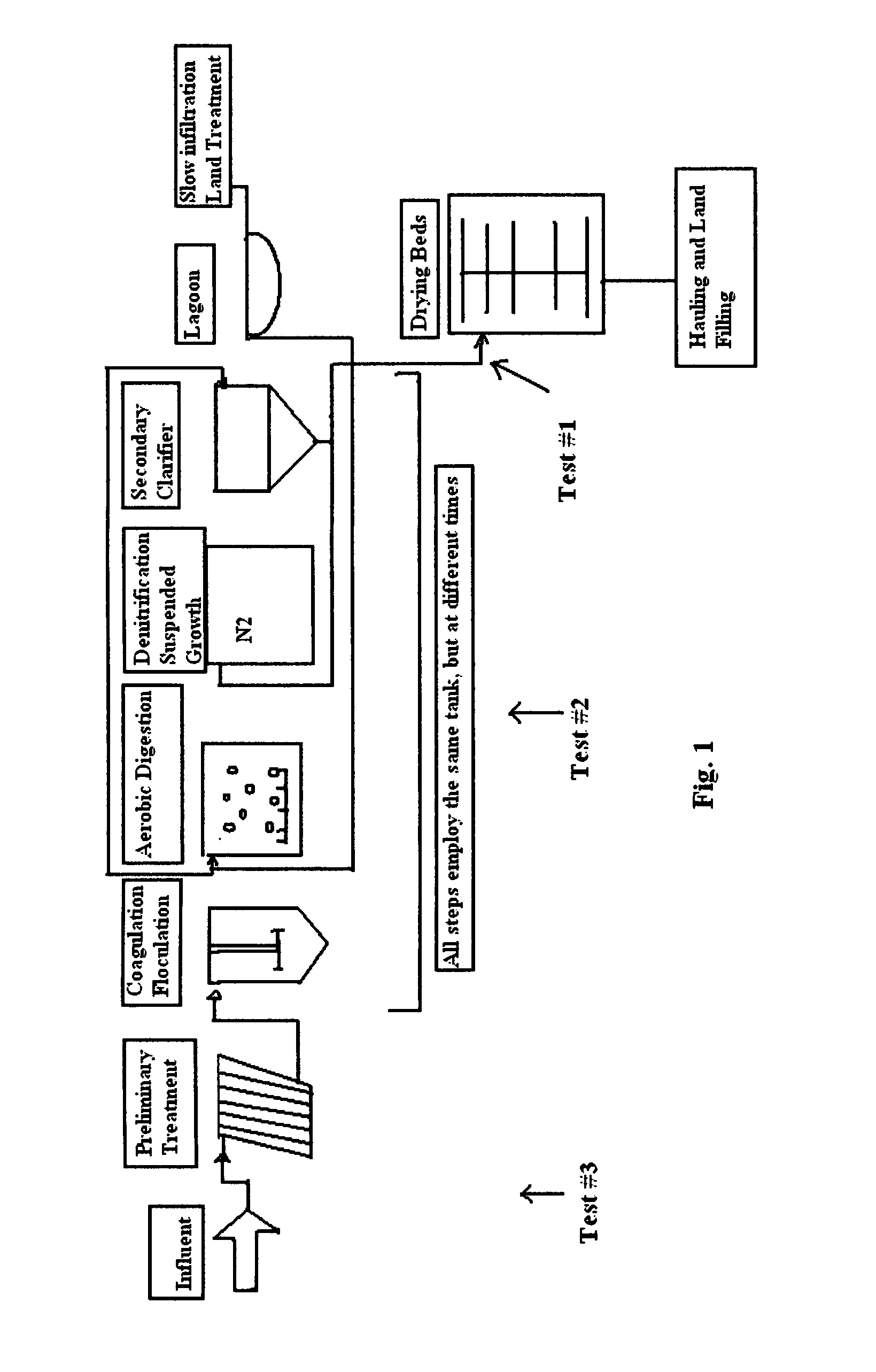
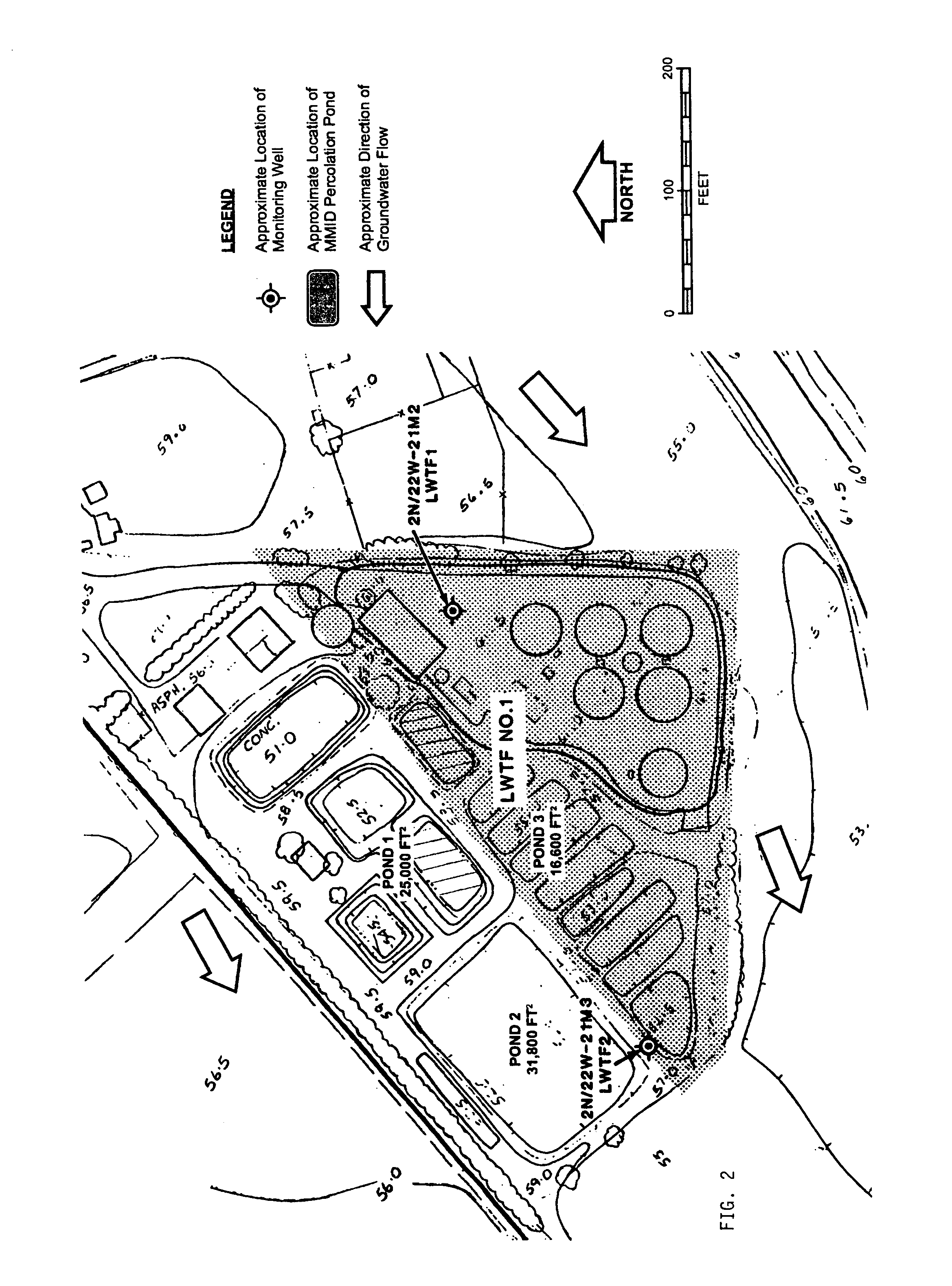
[0072]The method and apparatus of the present invention was field tested at the Montalvo Municipal Improvement District Water Pollution Control Plant in Ventura, Calif. for recovery of wastewater for land application. Montalvo Municipal Improvement District, a municipality owns the Montalvo Water Pollution Control Plant (Plant), located at 3555 Ventura Road, Montalvo, Calif. Treated domestic and commercial wastewaters are discharged under Waste Discharge Requirements contained in Order No. 87-092, adopted by the Regional Board on Jun. 22, 1987. The present wastewater treatment system shown in FIG. 1 consists of bar screening, comminuting, influent holding tank, two independent sequencing aerobic and denitrification batch reactors, with discharge into a final lined polishing pond. No off-site transfer or usage of treated wastewater is presently employed. The waste activated wastewater liquids between the floating and settling solids is extracted and discharged to the subsurface throu...


PUM

PropertyMeasurementUnit
Concentrationaaaaaaaaaa
Sizeaaaaaaaaaa
Particle sizeaaaaaaaaaa

Abstract

A chemical / biological wastewater treatment plant method and apparatus employing rapid sludge chemical dewatering technology in conjunction with an environmental biological system for treating the separated treated wastewater by land applying it for plant consumption, and / or passing it through aqueous plant or microbial reduction of the dissolved solids and ammonia for BOD compliance to produce water of sufficient quality to meet open stream and ocean effluent discharge requirements; and disposing of the high BTU low moisture solids.

Description

BACKGROUND OF THE INVENTION[0001]1. Field[0002]This invention comprises a rapidly installed wastewater treatment plant solids and liquids recovery system apparatus and method employing chemical dewatering and biological treatment technology.[0003]2. State of the Art[0004]Various sewage treatment methods and plants are known. Most large municipal systems employ a series of settling ponds sequentially concentrating the solids contained in wastewater either with or without polymers for separation from liquids via mechanical separation means, such as belt presses. In order to produce a clean effluent that can be safely discharged to watercourses, wastewater treatment operations use three or four distinct stages of treatment to remove harmful contaminants; according to the United Nations Environmental Programme Division of Technology, Industry, and Economics Newsletter and Technical Publications Freshwater Management Series No. 1, “Biosolids Management: An Environmentally Sound Approach ...

Claims


Application Information

Patent Timeline
IPC IPC(8): C02F3/00C02F11/121C02F11/143
CPCC02F3/301C02F3/302C05F17/00C02F1/66C02F11/121C02F11/14C02F2101/20C02F2303/02C02F2303/04C02F2303/24C02F2303/26C02F11/16Y10S210/916Y02P20/145Y02W30/40C02F11/143
Inventor THEODORE, MARCUS G.
Owner EARTH RENAISSANCE TECH
Why Eureka
Try Eureka