
Method and device for polishing endless belt metal rings for continuously variable transmission

a technology of continuous transmission and metal rings, which is applied in the direction of grinding feeders, manufacturing tools, mechanical equipment, etc., can solve the problems of deterioration of yield, metal rings colliding with one another, non-uniform polishing of inner and outer corners of the side edge of the metal ring, etc., and achieves good efficiency, good efficiency, and good efficiency.

Inactive Publication Date: 2008-08-19
HONDA MOTOR CO LTD
View PDF19 Cites 8 Cited by
  • Summary
  • Abstract
  • Description
  • Claims
  • Application Information

AI Technical Summary

Benefits of technology

The present invention provides a method for polishing a thin-plate cylindrical metal ring for use in an endless belt of a continuously variable transmission. The method involves polishing the metal ring by first projecting it and then brush polishing one edge of it using a polishing brush. The metal ring is then inversed and the other edge is also polished using the brush. The method ensures that grinding stones do not stick to the surface of the ring, resulting in a good polishing precision. The load current value of the motor is detected and adjusted to control the polishing force. The method is efficient and effective in achieving a satisfactory polishing amount.

Problems solved by technology

However, when the barrel polishing is performed, more media abut on an outer peripheral surface side rather than the inner side of the metal ring, and this causes a disadvantage that the polishing of inner and outer corners of the side edge of the metal ring becomes nonuniform.
When the metal rings are projected into the barrel, and at the time of the barrel polishing, there is a possibility that the metal rings collide with one another and are scratched.
These metal rings are removed by inspection, but have been causes for deterioration of yield.
However, for the polishing by the grinding stone, since a shape of the side edge of the metal ring is influenced by that of the grinding stone, it is frequently necessary to change the grinding stone, and there is a disadvantage that operation efficiency drops.

Method used


Image

  • Method and device for polishing endless belt metal rings for continuously variable transmission
  • Method and device for polishing endless belt metal rings for continuously variable transmission
  • Method and device for polishing endless belt metal rings for continuously variable transmission

Examples


first embodiment

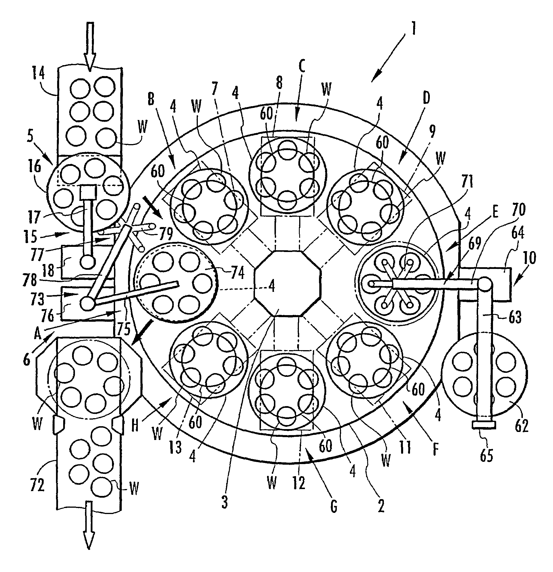
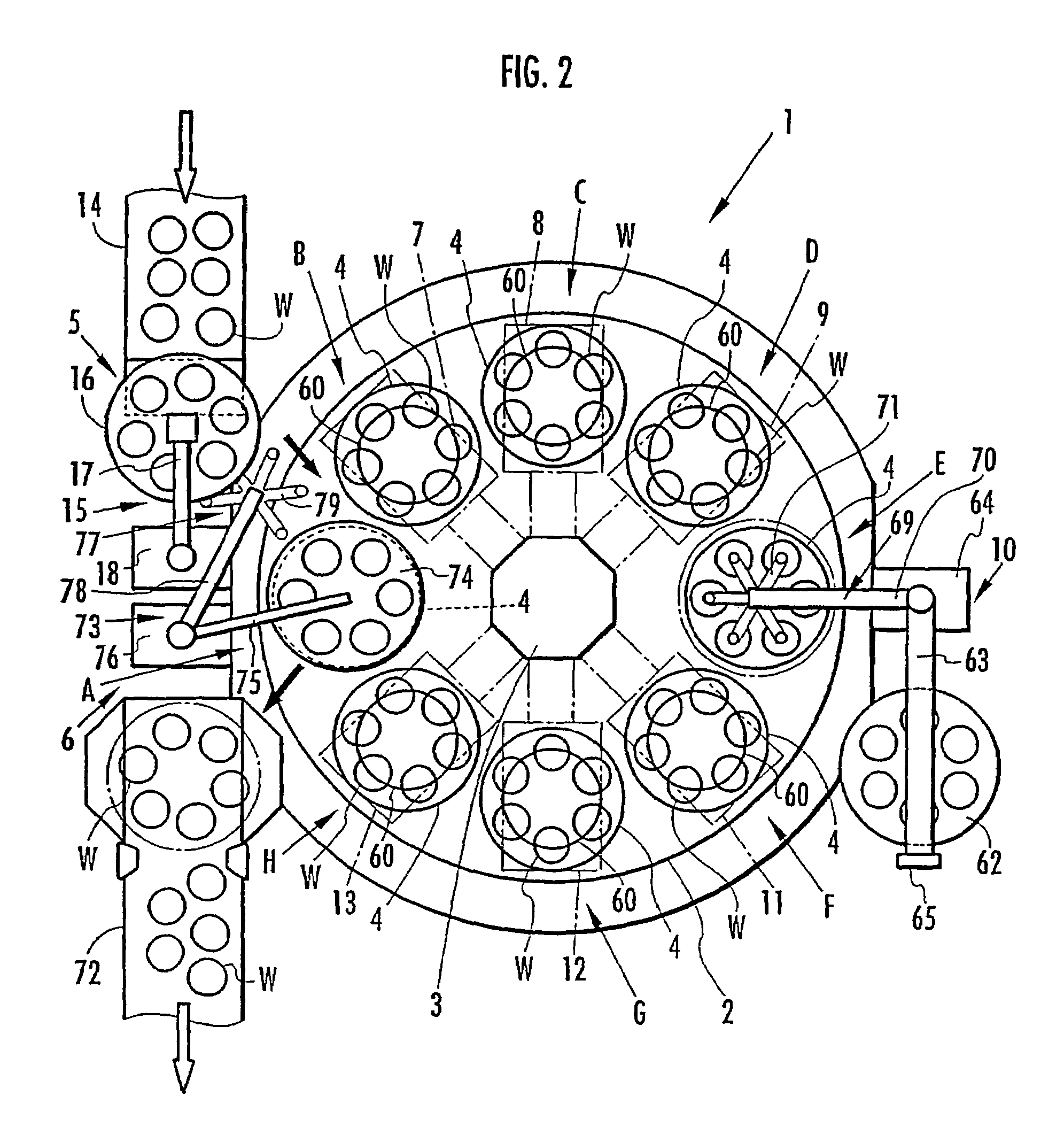
[0090]As shown in FIG. 2, a polishing device 1 in the present invention includes a turntable 2 for transferring the metal rings W. The turntable 2 is intermittently rotated around a support 3, and a plurality of holding tables 4 (eight holding tables 4 in the present embodiment) are disposed at a predetermined interval on a peripheral edge of the turntable. The holding table 4 holds a plurality of metal rings W (six metal rings W in the present embodiment) while the rings are arranged on the same circumference.

[0091]For the turntable 2, the metal ring W on the holding table 4 is stopped for a predetermined time and afterwards rotated at a predetermined angle for each of eight stages A to H, and the metal ring W is transferred among the respective stages A to H. In a rotation direction of the turntable 2, the stage A positioned in an uppermost stream is a projecting / clearing stage, and the projecting / clearing stage A includes projecting means 5 and clearing means 6. The stage B dispo...

second embodiment

[0122]In this manner, since the first turntable 81 and second turntable 82 are disposed in the polishing device 80 of the second embodiment, a plurality of stages such as the cleaning stages I1, I2 can additionally be disposed, and the metal ring W can be polished with higher precision.

[0123]Next, a third embodiment of the present invention will be described with reference to FIG. 16. It is to be noted that the components already described in the first embodiment are denoted with the same reference numerals in FIG. 16 and the description thereof is omitted. In a polishing device 83 of the third embodiment, as shown in FIG. 16, seven stages B to H are substantially linearly arranged without using the turntable 2. The first coarse polishing stage B includes the first coarse polishing means 7, the first intermediate polishing stage C includes the first intermediate polishing means 8, and the first finish polishing stage D includes the first finish polishing means 9. The inverting stage...


PUM

PropertyMeasurementUnit
incidence angleaaaaaaaaaa
outgoing angleaaaaaaaaaa

Abstract

There are disclosed a method and device for polishing a metal ring, which is capable of polishing a side edge of the metal ring without performing barrel polishing or polishing by grinding stones. Subsequently to a projecting step of projecting a metal ring W by clearing means 6, a first brush polishing step of polishing one edge of the metal ring W by a polishing brush 60 is performed. Subsequently, an inverting step of inverting the metal ring W whose one edge is polished by the first brush polishing step is inverted by the inverting means 10 is performed. Subsequently, a second brush polishing step of polishing the other edge of the metal ring W which is inverted by the inverting step by the polishing brush 60 is performed. Moreover, a clearing step of clearing the metal ring whose other edge is polished by the second brush polishing step by clearing means 7 is performed.

Description

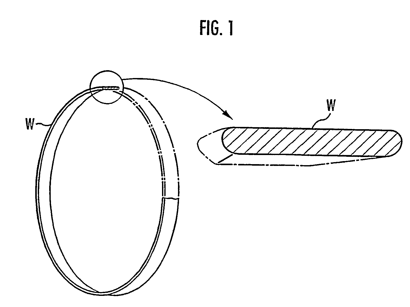
BACKGROUND OF THE INVENTION[0001]1. Field of the Invention[0002]The present invention relates to a method and device for polishing a thin-plate metal ring for use in an endless belt of a continuously variable transmission.[0003]2. Description of the Related Art[0004]For example, a plurality of elements stacked / arranged in an annular form and bound by a laminated ring constituted by stacking a plurality of metal rings have been used in a belt for power transmission for use in a continuously variable transmission. The metal ring constituting this type of laminated ring is formed in an endless band shape by slicing a cylindrical metal drum every predetermined width by a thin disc shaped grinding stone. Moreover, since burrs are generated in a side edge of the metal ring cut from the cylindrical drum, it is necessary o polish the burrs. Even when a few burrs are generated in the side edge of the metal ring, it is necessary to polish the side edge of the metal ring and to finish the side...

Claims


Application Information

Patent Timeline
Patent Type & Authority Patents(United States)
IPC IPC(8): B24B9/00B24B29/02B24B41/00F16G5/16
CPCB24B9/00B24B29/005B24B29/02B24B41/005F16G5/16
Inventor YOSHIMURA, TAKESHIMINOWA, YOSHIYUKIMARUYAMA, TSUTOMUMINEGISHI, SEIICHIWATANABE, YASUOWATABE, YOSHIHARUHAGA, FUMITAKANAKAJIMA, KATSUYUKIKURIYAMA, SHINICHINAGAO, YUICHI
Owner HONDA MOTOR CO LTD
Learn More