
Fermentation flask for cultivating microorganisms

a technology of fertilization flask and microorganism, which is applied in the direction of transportation and packaging, rigid containers, after-treatment of biomass, etc., can solve the problems of high cost of making tuna flasks that must be reused, contamination of samples cultivated in reused flasks, and use of baffles, so as to reduce costs and contamination, increase the agitation of biological materials, and increase the growth of materials.

Active Publication Date: 2008-06-03
SCI PLASTIC PRODS
View PDF17 Cites 26 Cited by
  • Summary
  • Abstract
  • Description
  • Claims
  • Application Information

AI Technical Summary

Benefits of technology

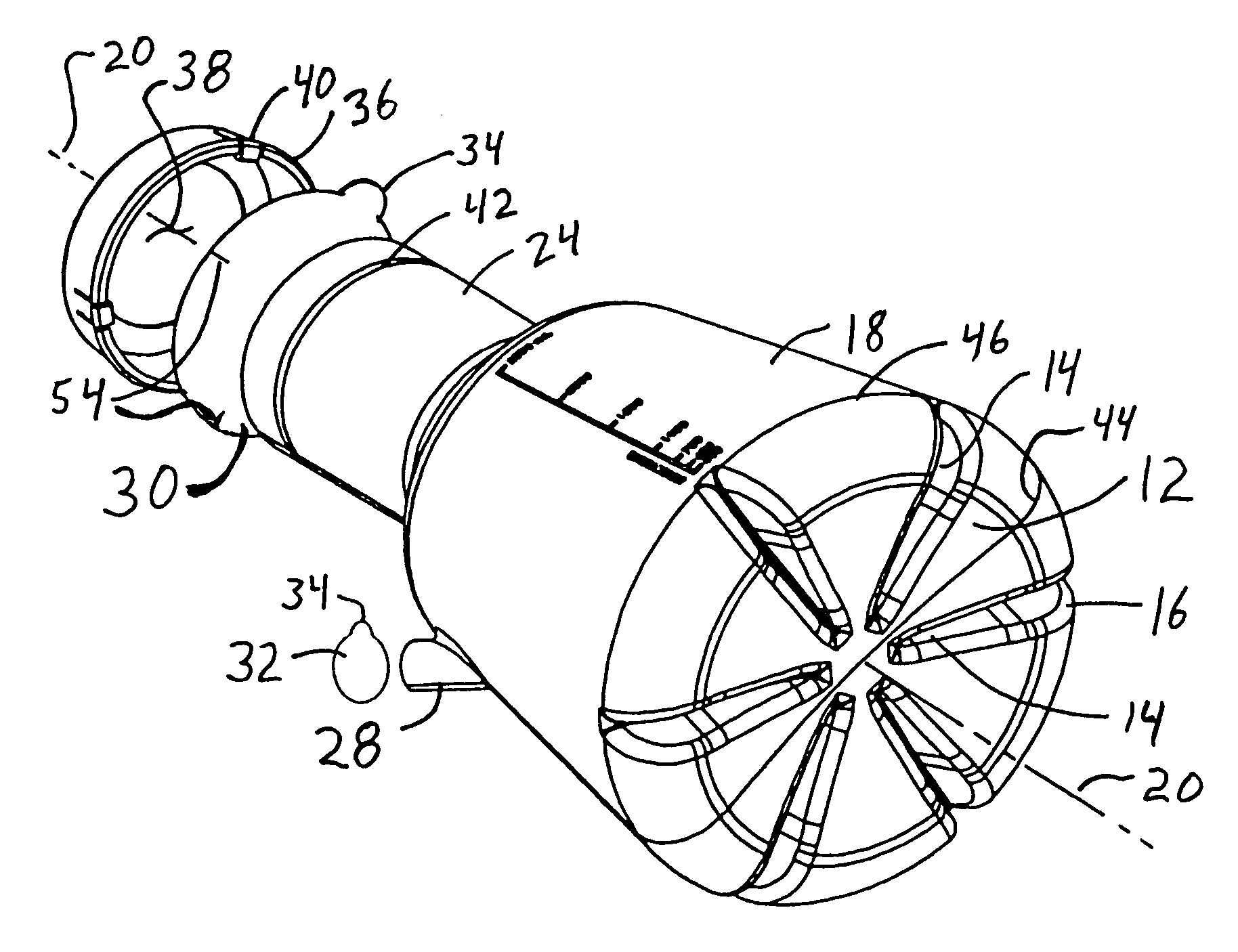
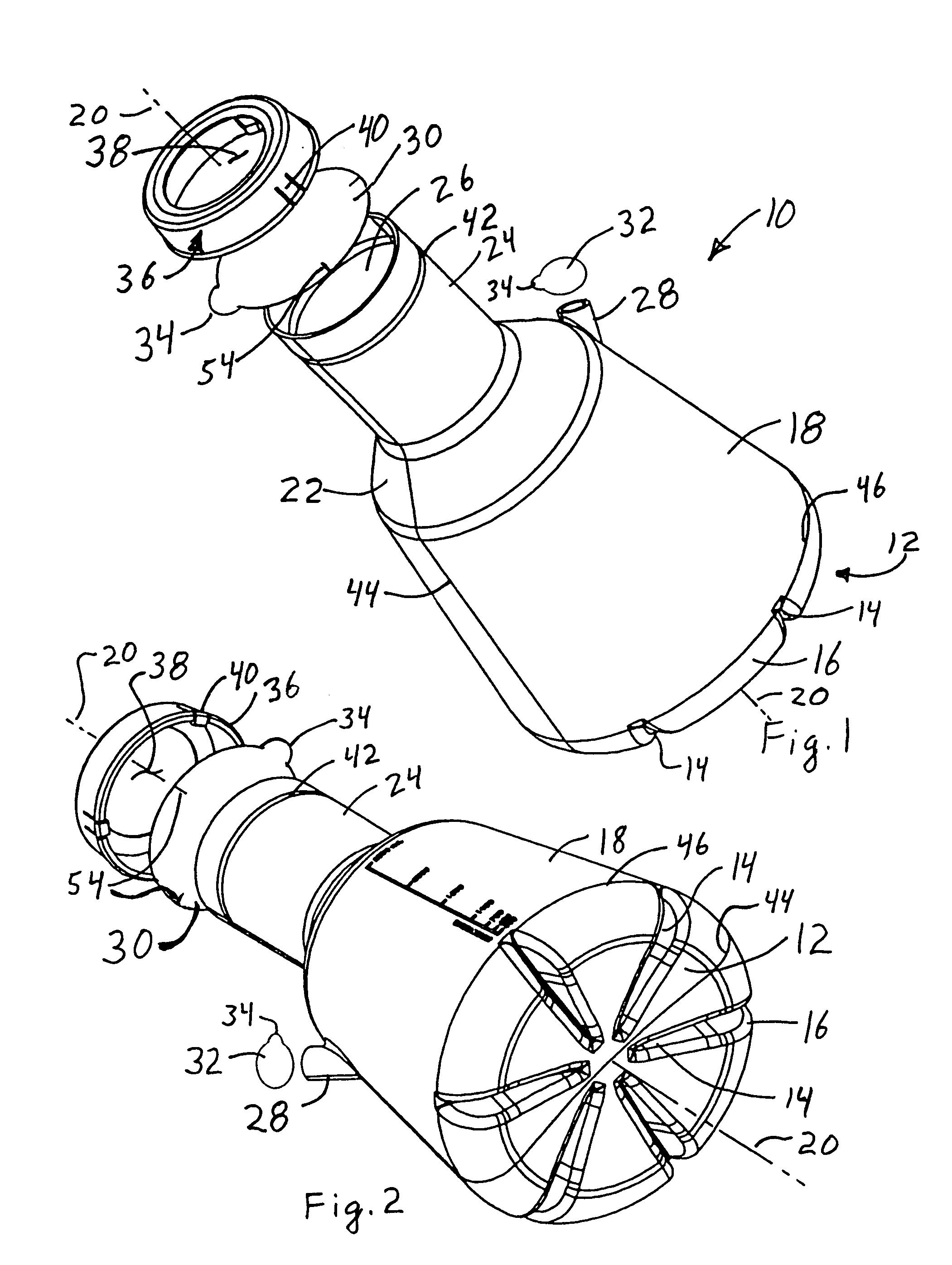
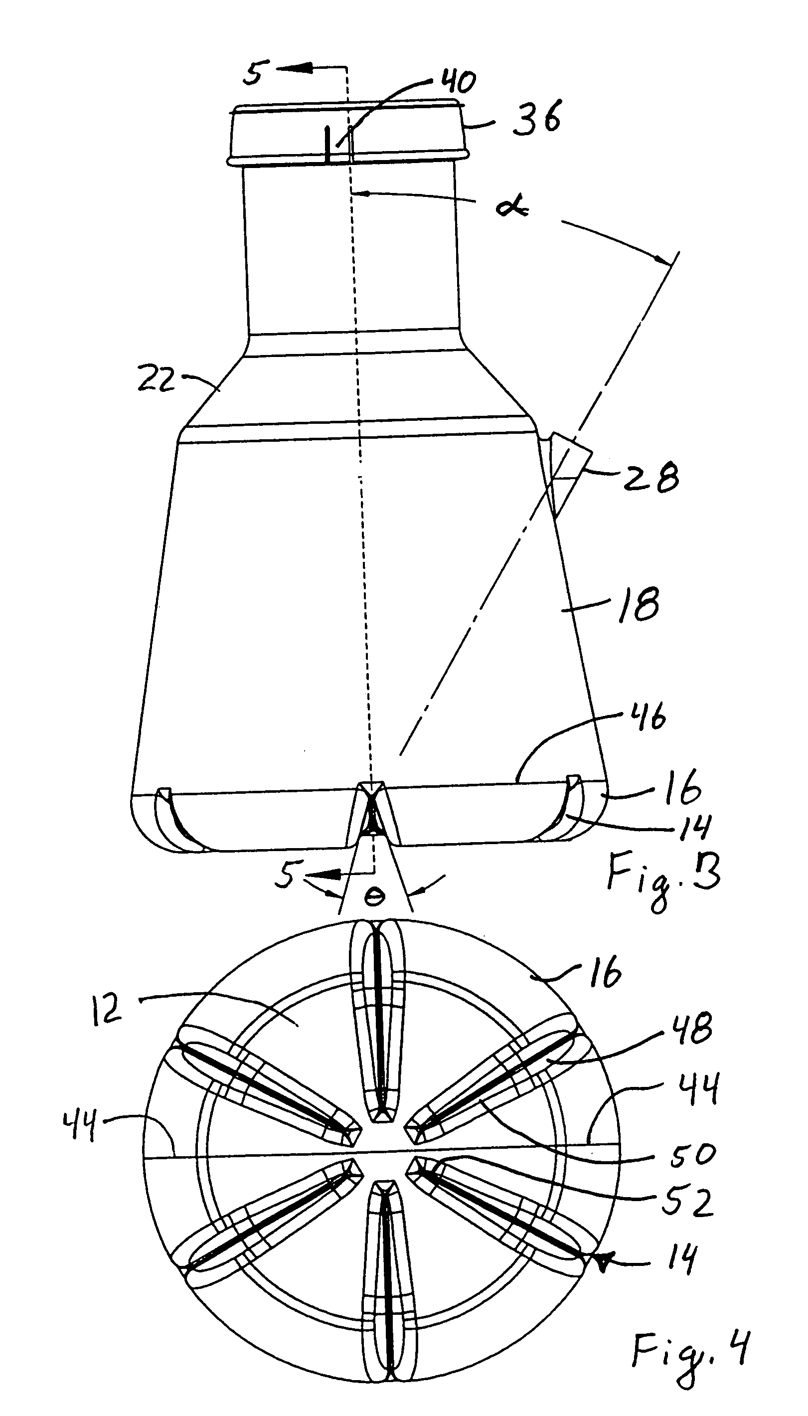
[0007]A blow-molded, disposable flask is provided to reduce costs and contamination. The flask has a bottom with specially located and shaped baffles which increase the agitation of the biological material and cause a surprisingly consistent and increased growth of the material. The flask preferably has a bottom with rounded peripheral edges joining a conical sidewall that tapers inward slightly until it reaches a height of about the same as the diameter of the bottom. A short, inwardly tapered transition area joins a neck to the bottom wall, with the neck having a diameter that is about half the diameter of the bottom. The neck ends in an opening that is covered by a circular sheet of disposable filter material which preferably has adhesive on one side to removably fasten the filter over the opening and to the neck of the flask. The disposable filter allows ample oxygen access while providing a reduction in the risk of contamination and reducing costs. A finger tab extending from the filter allows easy attachment and removal of the filter without touching the surface exposed to the inside of the flask. A ring-shaped cap with an open top can be optionally used to hold or to help hold the filter over the opening. A pipette access port can optionally be formed in the bottom or transition portion of the flask. The access port is preferably located about 6 inches or less from the center of the bottom of the flask in order to accommodate a wider range of pipette sizes than previously usable while reducing the risk of contamination, and spilling of the contents. The pipette port can be covered by a smaller version of the filter covering the flask opening to further reduce the risk of contamination.

Problems solved by technology

But Tunac's use of these baffles, including the internal baffles to inhibit the fluid from splashing out of the flask, has significant disadvantages.
The cost of making the Tunac flasks is high enough that they must be reused.
Unfortunately, reuse requires cleaning the flasks and filters in an autoclave and despite such cleaning it is not uncommon to have sufficient contaminants remain that reuse of the flask contaminates the samples cultivated in the reused flask.
The use of the prior art containers, such as Tunac, often produce inconsistent growth rates, in part due to residual contamination arising from reuse.
But the cap and filter in Tunic's container are expensive to make, and are thus reused, resulting in a risk of contamination and high operating costs.
As the containers become larger longer pipettes are needed, and laboratory personnel sometimes tilt the containers and spill everything out in using the pipettes.
Further, removing and reattaching the caps to access the containers sometimes contaminates the caps.

Method used


Image

  • Fermentation flask for cultivating microorganisms
  • Fermentation flask for cultivating microorganisms
  • Fermentation flask for cultivating microorganisms

Examples


Embodiment Construction

[0016]Referring to FIGS. 1–5, a container 10 is provided having a bottom 12 with a plurality of baffles 14 formed in the bottom. The bottom 12 has a curved peripheral corner 16 which joins sidewall 18 that angle inward toward longitudinal axis 20 to form a conical structure. A transition area 22 joins the sidewalls to an elongated neck 24 having an opening 26 in a distal end of the neck. An access port 28 is formed in the side of the container, advantageously in either the transition area 22 or sidewall 18. A first filter 30 covers the opening and a second filter 32 optionally covers the access port, each filter having a finger tab 34 to facilitate handling and removal of the filter. A cap 36 optionally holds the first filter 30 onto the neck 24. The cap 36 preferably comprises an annular flange with an opening 38 about as large as the opening 26 in the neck 24. Resilient locking tabs 40 are cut or formed in the flange of the cap 36, with distal ends of the locking tabs 40 engaging ...


PUM

PropertyMeasurementUnit
included angleaaaaaaaaaa
heightaaaaaaaaaa

Abstract

A container is provided for cell growth by artificial cultivation of selected biological material in a growth liquid for use in an oscillating incubator. The container has a circular bottom with rounded corners joining a sidewall that is inclined at an angle toward a longitudinal axis of the container to define a container volume. The bottom has six equally spaced baffles extending inward from the corners and upward toward a large diameter opening of the container centered on the longitudinal axis. The baffles have a triangular cross-sectional shape with an included angle of about 28–40°, and a height measured parallel to the longitudinal axis of about 15–25% of the usable container volume. The baffles end before the longitudinal axis. The container and baffles are blow molded of a polymer suitable for blow molding. An air permeable filter is placed over the container opening, with the filter having an adhesive on one side to stick to the container. A finger tab on the periphery of the filter helps position and remove the filter.

Description

BACKGROUND OF THE INVENTION[0001]This invention relates to flasks or containers and systems used for aerobic fermentation used to cultivate the aerobic growth of microorganisms, cell lines or other biological organisms.[0002]For a variety of biotechnology applications there is a need to take a few biological organisms and as quickly as possible, multiply or grow them into significantly larger numbers of organisms. The biological growth usually increases with the oxygen level.[0003]One common method of cultivating biological organisms is to place them in a flask in a liquid medium, and then oscillate the flask at a predetermined rate in an enclosed incubator. This approach can use a flask disclosed in a patent to Tunac, U.S. Pat. No. 4,665,035, which flask uses specific patterns of baffles on the bottom and neck of the flask. But Tunac's use of these baffles, including the internal baffles to inhibit the fluid from splashing out of the flask, has significant disadvantages. The cost o...

Claims


Application Information

Patent Timeline
Patent Type & Authority Patents(United States)
IPC IPC(8): C12M1/34C12M1/24B01L3/08C12M1/02C12M1/12C12N1/00C12N5/02
CPCC12M23/08C12M23/20C12M27/16Y10S215/01Y10S215/08C12N1/20
Inventor ELLIS, SAMUEL A.HARLAN, JEFFREY L.
Owner SCI PLASTIC PRODS
Learn More