
Electromechanical memory cell with torsional movement

a technology of electronic memory and torsional movement, applied in the field of nonvolatile electronic memory, can solve the problems of loss of information stored in the ram, poor energy efficiency of some read/write memories, and unsatisfactory performance of some rams

Inactive Publication Date: 2008-03-25
XEROX CORP
View PDF15 Cites 22 Cited by
  • Summary
  • Abstract
  • Description
  • Claims
  • Application Information

AI Technical Summary

Benefits of technology

The MEMS memory cell achieves significant reductions in power consumption and voltage requirements, with writing efficiency improved by 14 times compared to traditional nonvolatile semiconductor memories, and enhanced radiation resistance, making it suitable for applications requiring low power and radiation hardness.

Problems solved by technology

While semiconductor memories have achieved many of these goals, their performance is not ideal in some respects.
For example, the energy efficiency of some read / write memories is relatively poor, and most transistor memories are sensitive to radiation.
Typically, the information stored in these RAMs is lost if the supply power is turned off.
While flash memories have many advantages as nonvolatile memories, their energy efficiency is relatively poor during the programming process.
Therefore, the efficiency of these injection / tunneling processes is poor.
The low efficiency, and the requirement of a high supply voltage, limits the usefulness of flash memories, especially in applications that require a low supply voltage and low power consumption.
In addition to energy efficiency, one of the major drawbacks of semiconductor memories is that they are sensitive to radiation.
However, these approaches typically require more complicated fabrication processes or packaging, which introduce a higher cost.

Method used


Image

  • Electromechanical memory cell with torsional movement
  • Electromechanical memory cell with torsional movement
  • Electromechanical memory cell with torsional movement

Examples


Embodiment Construction

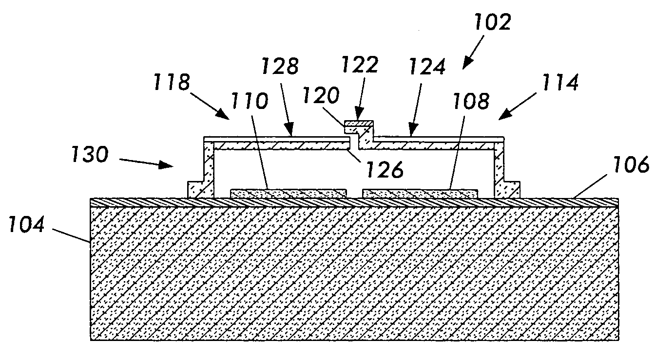
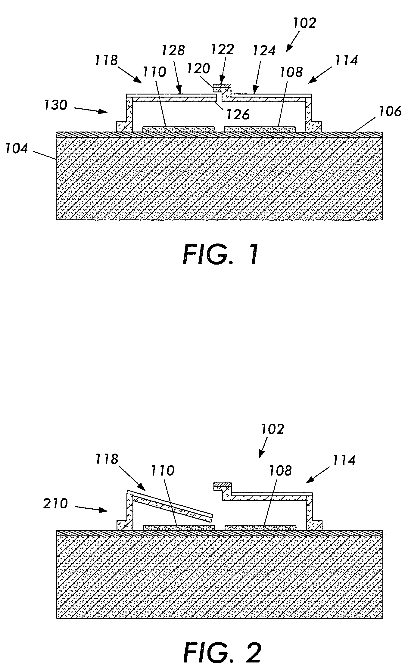
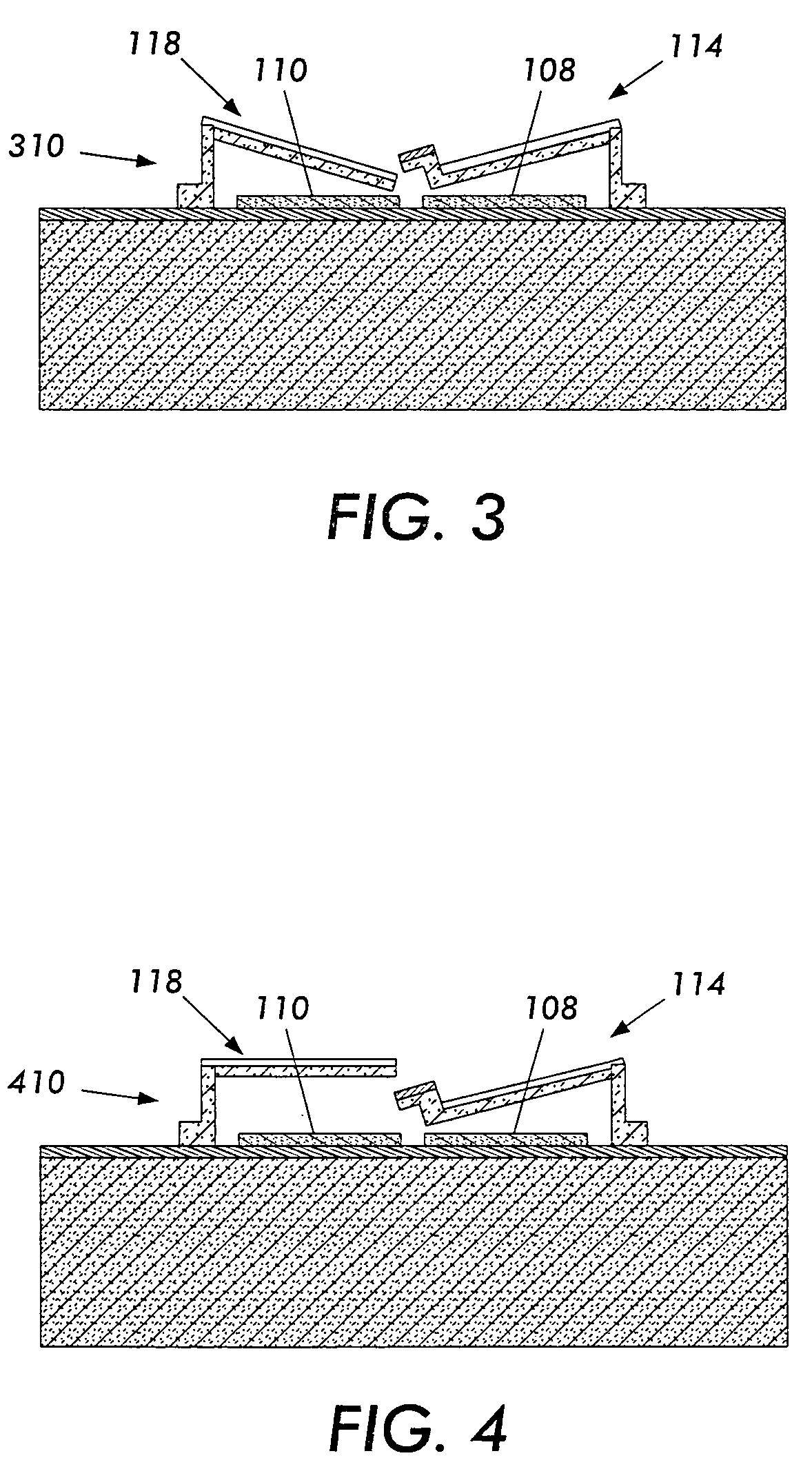
[0024]A nonvolatile memory device that overcomes the high supply voltage, writing efficiency, and radiation susceptibility limitations of flash memory is implemented using Micro-electromechanical Systems (MEMS) technology. MEMS technology is used to create a pair of cantilevers that are used as a memory cell. The memory cell is simple to both use and manufacture. For example, the memory cell can be implemented using a MEMS technology that allows for CMOS addressing circuitry to be integrated on the same chip. Therefore, the whole memory system can be fabricated at a low cost. The latch can be switched between on and off states using for example, electrostatic or magnetic forces or thermal movement. Data stored in the memory is read out as, for example, a capacitance or a resistance measurement.

[0025]For example, the memory cell comprises a pair of polysilicon cantilevers. The on and off state of this mechanical latch is switched by using electrostatic forces applied sequentially on ...


PUM


Abstract

A memory cell uses a pair of cantilevers to store a bit of information. Changing the relative position of the cantilevers determines whether they are electrically conducting or not. The on and off state of this mechanical latch is switched by using, for example, electrostatic, electromagnetic or thermal forces applied sequentially on the two cantilevers to change their relative position. The amount of power required to change the state of the cell is reduced by supporting at least one of the cantilevers with at least one lateral projection that is placed in torsion during cantilever displacement. After a bit of data is written, the cantilevers are locked by mechanical forces inherent in the cantilevers and will not change state unless a sequential electrical writing signal is applied. The sequential nature of the required writing signal makes inadvertent, radiation or noise related data corruption unlikely.

Description

BACKGROUND[0001]Aspects of the present disclosure in embodiments thereof are related to a non-volatile electronic memory. The memory finds particular application where low power consumption, and / or low writing voltage requirements are advantageous. Additionally, embodiments find application where increased radiation immunity is desired.[0002]Memory devices play an important role in modern microelectronic systems. For example, memory devices store instruction sets, programs, and / or data for computer processors. Electronic systems use memory devices for example, when performing calculations, signal processing, or data analysis. There are many different memory architectures used for storing information. For example, some moving surface memories store data in the form of magnetic dipoles. Magnetic tapes and discs are examples of these kinds of memory devices. Compact disks store information by varying optical characteristics of points on the surface of the disk. Semiconductor memories t...

Claims


Application Information

Patent Timeline
Patent Type & Authority Patents(United States)
IPC IPC(8): G11C11/00
CPCB82Y10/00G11B9/04G11B9/06G11C23/00
Inventor LIN, PINYENCHEN, JINGKUANGMA, JUN
Owner XEROX CORP
Learn More