System and method for driving synchronous motor
a synchronous motor and control system technology, applied in the direction of motor/generator/converter stopper, electronic commutator, dynamo-electric converter control, etc., can solve the problem of system inability to determine the correct rotor position, the system cannot detect the sudden change of load torque, and the observation cycle of the terminal voltage is reduced, so as to improve the load follow-up performance. performance and the effect of reducing the observation cycl
- Summary
- Abstract
- Description
- Claims
- Application Information
AI Technical Summary
Benefits of technology
Problems solved by technology
Method used
Image
Examples
embodiment 1
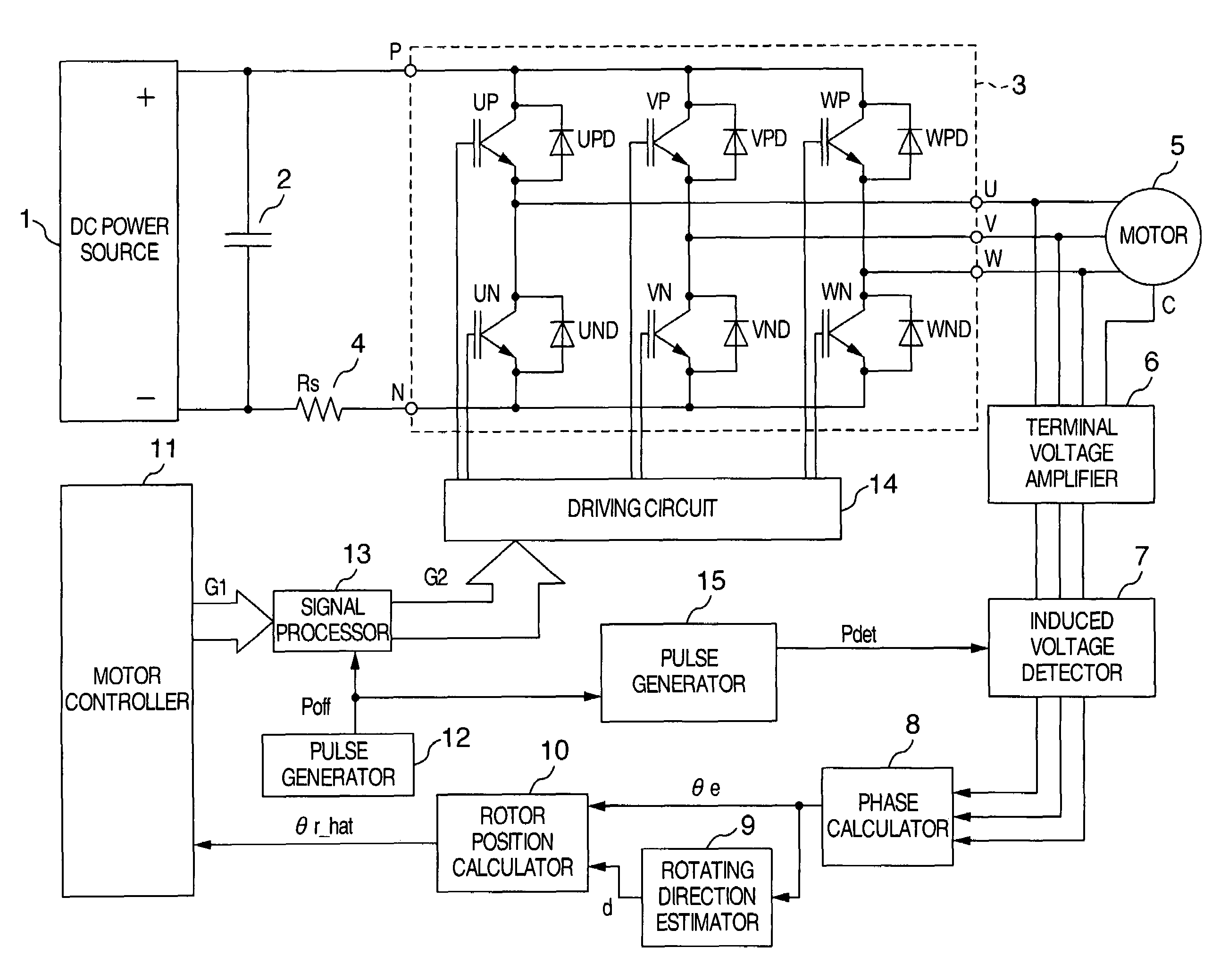
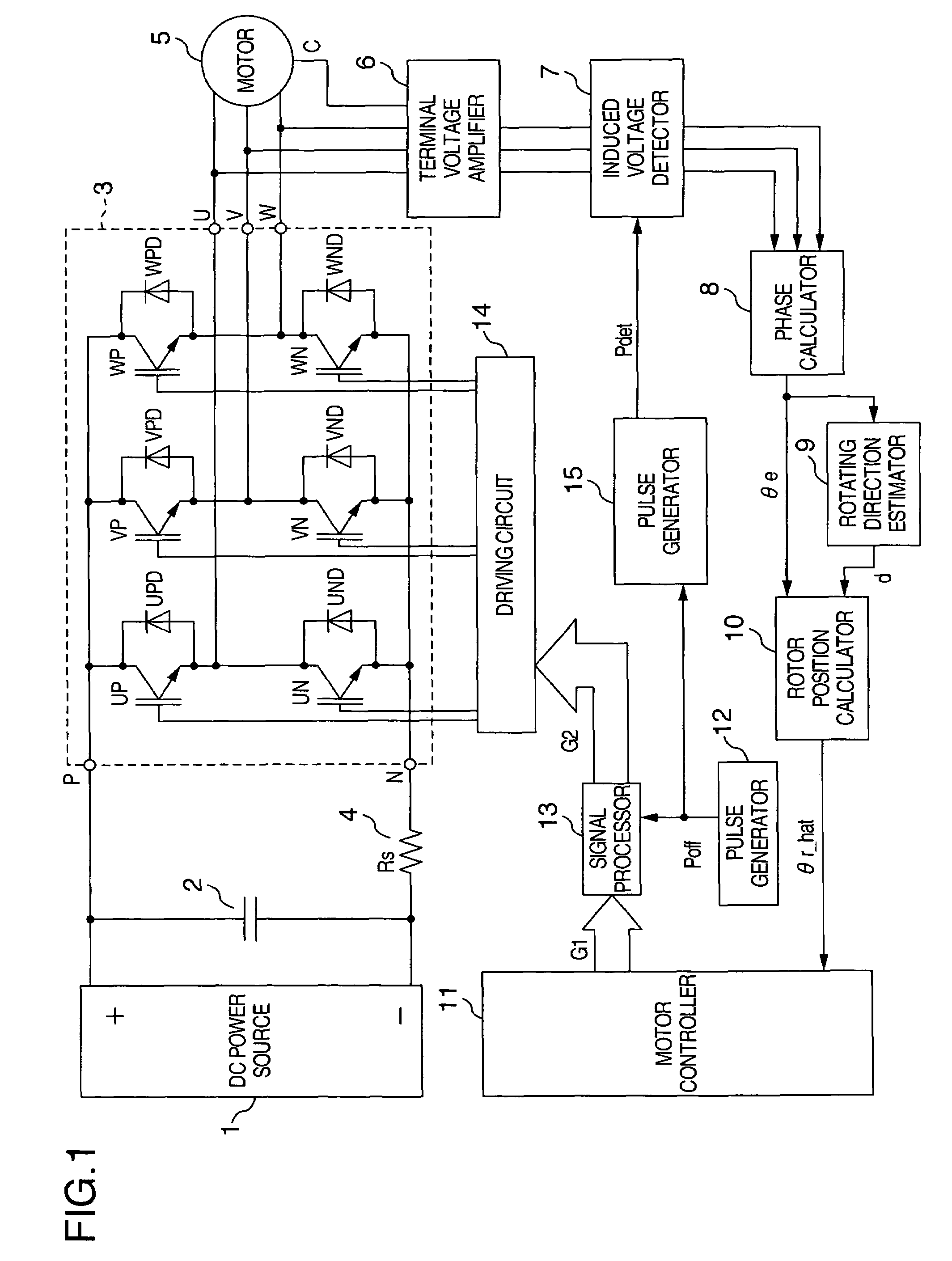
[0033]FIG. 1 shows a structural view of this embodiment. A capacitor 2 for smoothing a DC voltage is connected between a positive terminal and a negative terminal of a DC power source 1. The positive terminal of the capacitor 2 is connected with a DC positive terminal P of inverter 3. A DC negative terminal N of an inverter 3 is connected to the negative terminal of the capacitor 2 through a shunt resistor 4. AC terminals U, V and W of a synchronous motor 5 such as a permanent magnet synchronous motor as a control object are connected to AC output terminals of the inverter 3. The synchronous motor 5 is driven by three-phase AC power supplied by the inverter 3.
[0034]A terminal voltage amplifier 6 is connected to the AC terminals (U, V, W) of the synchronous motor 5 and to a neutral terminal C of a stator winding. The terminal voltage amplifier 6 multiplies the voltage between the AC terminal (U, V, W) and the neutral terminal C by a predetermined gain and outputs the product as a ter...
embodiment 2
[0072]In this embodiment, the wait time Tw is set by measuring the current decrease in the free wheel mode. FIG. 13 shows a structural view of this embodiment. Only different portions of the construction will be explained in comparison with FIG. 1 showing the first embodiment. A voltage across both ends of the shut resistor 4 is converted to a current signal IDC by the current detector 16. The current signal IDC is connected to the pulse generator 15.
[0073]The current path in the free wheel mode contains the shunt resistor 4 as can be seen from FIG. 10. Therefore, when the voltage across both ends of the shunt resistor 4 is measured, the timing at which the current in the free wheel mode becomes zero can be acquired. The pulse generator 15 shown in FIG. 13 changes the induced voltage detection signal Pdet to the H level simultaneously with the time at which the current signal IDC becomes zero after the change of the all-OFF control pulse signal Poff to the H level or with a predeter...
embodiment 3
[0075]In the motor driving apparatuses of the first and second embodiments shown in FIGS. 1 and 13, the value of the back electromotive force KE of the motor during driving is measured in this embodiment and control is executed while the set value is corrected. The explanation will be hereinafter given.
[0076]To estimate the rotor position, the induced voltage of the synchronous motor 5 during driving is measured in this embodiment. Because the induced voltages of two or more phases are detected, the peak value of the induced voltage can be determined from the measured voltage unless the output of the induced voltage detector 7 gets into saturation.
[0077]When the terminal voltage amplifier 6 employs the phase voltage detection system shown in FIG. 4A, the peak value of the induced voltage in the phase voltage can be determined by using α and β obtained from equation (1).
|E|=√{square root over (α2+β2)}=g·KEωm (11)
[0078]It is possible to consider the angular frequency ω1 of the voltag...
PUM
 Abstract
Description
Claims
Application Information
 - R&D
- Intellectual Property
- Life Sciences
- Materials
- Tech Scout
- Unparalleled Data Quality
- Higher Quality Content
- 60% Fewer Hallucinations
Browse by: Latest US Patents, China's latest patents, Technical Efficacy Thesaurus, Application Domain, Technology Topic, Popular Technical Reports.
© 2025 PatSnap. All rights reserved.Legal|Privacy policy|Modern Slavery Act Transparency Statement|Sitemap|About US| Contact US: help@patsnap.com


