
Closed loop resource allocation

a closed loop and resource allocation technology, applied in the field of wireless communications, can solve the problems of imposing stringent and fixed delay requirements, waste of resources, delay in the decision-making process, etc., and achieve the effects of ensuring resource allocation fairness, high burstness, and flexible us

Inactive Publication Date: 2008-03-04
QUALCOMM INC
View PDF27 Cites 13 Cited by
  • Summary
  • Abstract
  • Description
  • Claims
  • Application Information

AI Technical Summary

Benefits of technology

[0020]It is another objective of the present invention to prevent a subscriber station from creating unacceptable interference to candidate base stations by its reverse link transmission, thus enforcing candidate set protection.
[0026]It is yet another objective of the present invention to provide soft multi-bit busy tones that indicate not only whether a base station is in an overload condition or not, but also provides some indication of the extent of its loading.

Problems solved by technology

A significant difference between voice services and data services is the fact that the former imposes stringent and fixed delay requirements.
In principle, information can be exchanged between the network and the subscribers, but this involves signaling over the air interface which implies a waste of resources and a delay in the decision making process.
A first problem is therefore to design a medium access control strategy for the reverse link that exploits in an optimal way the available information minimizing signaling messages.
Another fundamental problem is resource allocation for a subscriber station in soft handoff.
Yet another fundamental problem is protection of base stations that are not in soft handoff with a particular subscriber station, but that nevertheless are connected to that subscriber station through an electromagnetic link with path loss comparable to those measured in the active set.
The base stations do not have this information absent a significant amount of signaling, which is undesirable.

Method used


Image

  • Closed loop resource allocation
  • Closed loop resource allocation
  • Closed loop resource allocation

Examples


Embodiment Construction

I. Method Overview

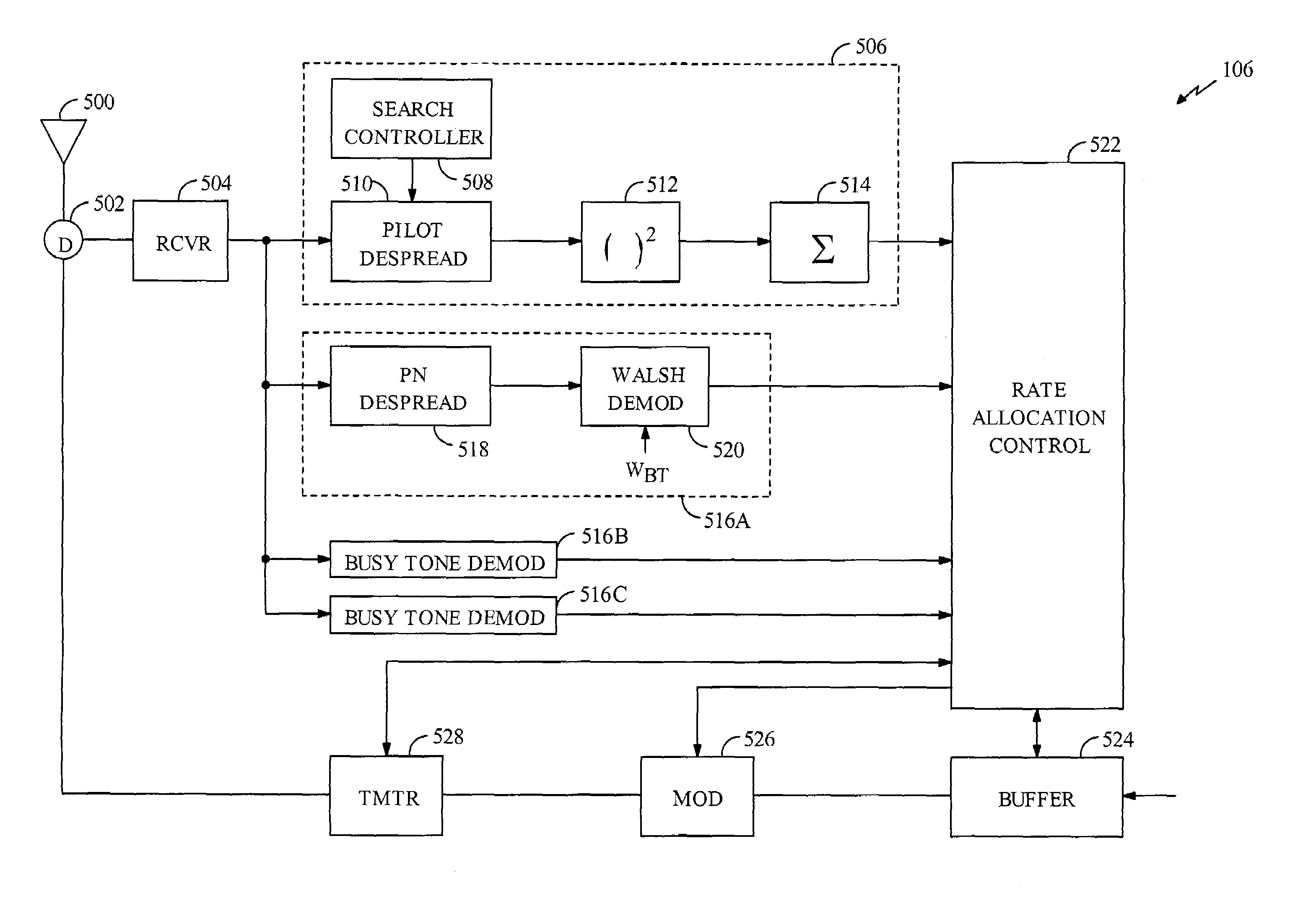
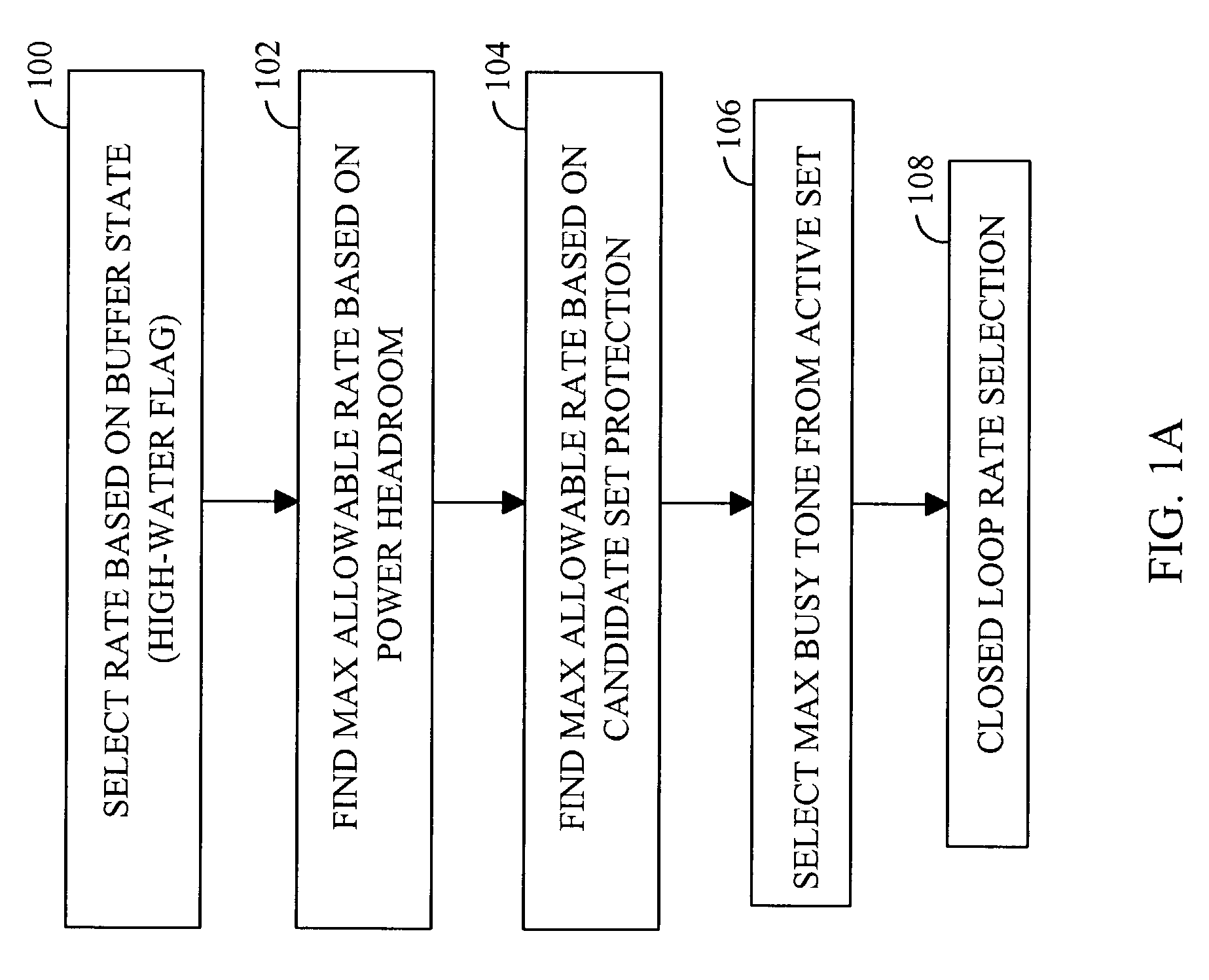
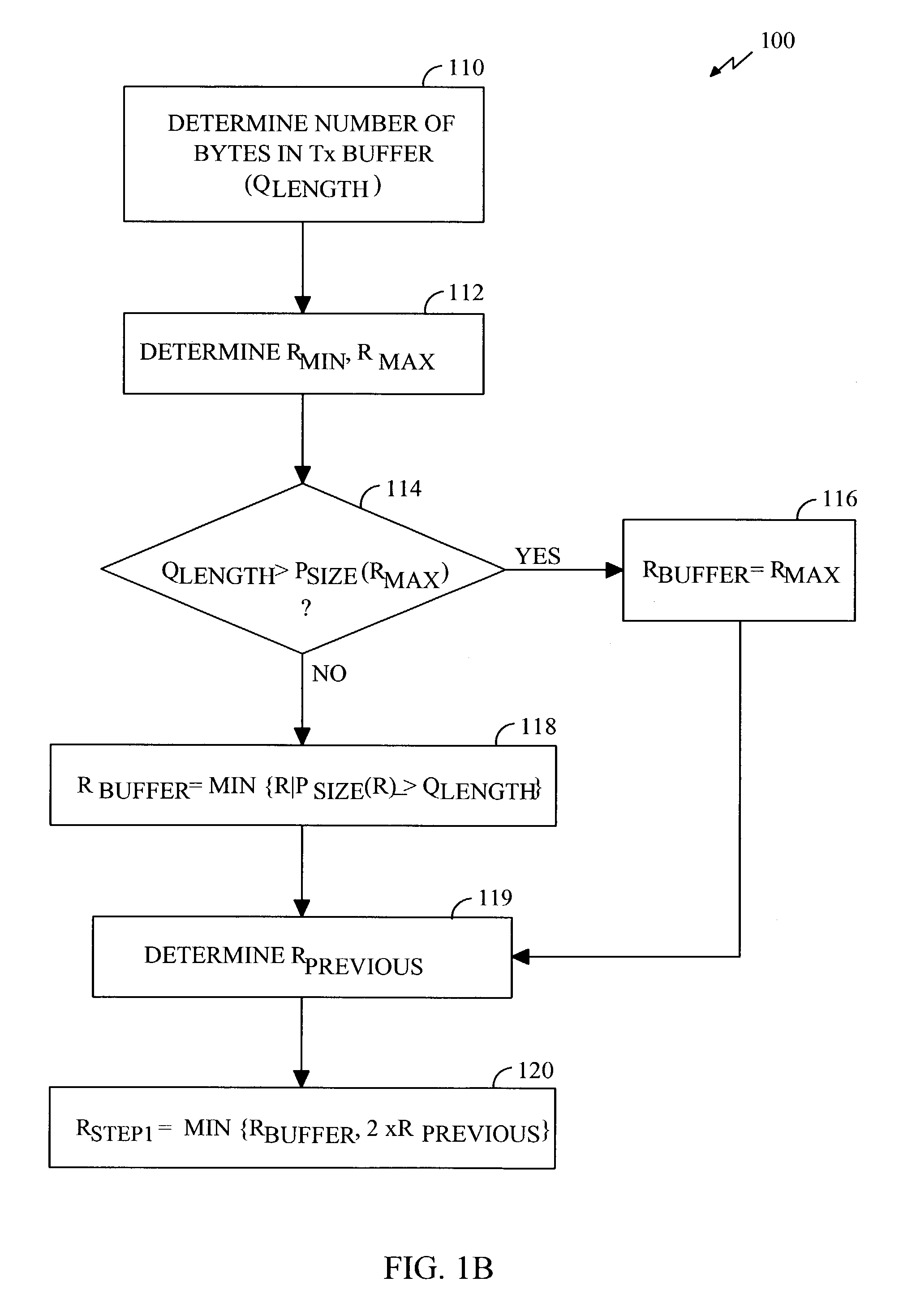
[0033]FIG. 1A is a flowchart describing the preferred method of performing closed loop resource allocation according to the present invention. It will be understood by one skilled in the art that the steps illustrated in FIG. 1A represent no preferred ordering sequence and that the order of the steps may be changed without departing from the scope of the present invention. Moreover, steps of the present invention may be eliminated altogether without departing from the scope of the present invention. In the exemplary embodiment, the present invention is employed to determine the data rate of reverse link transmissions from a subscriber station. In block 100, the subscriber station selects an initial desired rate (Rstep1) based on the buffer state. In the exemplary embodiment, the data rate is determined on a per packet basis.

[0034]FIG. 1B is a flowchart describing the rate selection based on the buffer state in greater detail. In block 110, the subscriber station de...


PUM


Abstract

Method and apparatus for performing transmission data rate allocation in a high speed wireless communications network. A macro control loop with the network of base stations on one side and all the subscriber stations on the other side. Subscriber station selects a rate based on the amount of data queued for transmission (100). Adjusts this rate based on the available power headroom of the subscriber station (102). This adjusted transmission rate is then adjusted again to account for protection of base stations in the candidate set of the subscriber station (104). This rate is then adjusted in accordance with busy tone signals indicative of the loading conditions of active set base stations of the subscriber station (108). The base stations react to these action by refreshing measurements of their instantaneous traffic load and providing feedback in the form of soft busy tones. The algorithm is named Closed Loop Resource Allocation.

Description

CLAIM OF PRIORITY UNDER 35 U.S.C. §120[0001]The present Application for Patent is a Continuation and claims priority to patent application Ser. No. 09 / 409,981, entitled “CLOSED LOOP RESOURCE ALLOCATION,” filed Sep. 30, 1999 now U.S. Pat. No. 6,563,810, now allowed, and assigned to the assignee hereof and hereby expressly incorporated by reference herein.BACKGROUND[0002]I. Field of the Invention[0003]The present invention relates to wireless communications. More particularly, the present invention relates to a novel and improved method and apparatus for determining the transmission data rates in a high speed wireless communication system.[0004]II. Description of the Related Art[0005]A modern day communication system is required to support a variety of applications. One such communication system is a code division multiple access (CDMA) system which conforms to the “TIA / EIA / IS-95 Subscriber station-Base Station Compatibility Standard for Dual-Mode Wideband Spread Spectrum Cellular Sys...

Claims


Application Information

Patent Timeline
Patent Type & Authority Patents(United States)
IPC IPC(8): H04J1/16H04B7/216H04J3/16H04B7/005H04L1/00H04W28/22H04W36/18H04W52/26H04W52/34H04W52/40H04W72/54
CPCH04L1/0002H04W28/22H04W52/343H04W52/367H04W52/40H04B2201/70705H04W36/18H04W52/26H04W52/267H04W72/04H04W72/02H04W72/0473
Inventor CORAZZA, GIOVANNI E.
Owner QUALCOMM INC
Learn More