
Methods of fabricating a single transistor floating body DRAM cell having recess channel transistor structure

a technology of dram cell and transistor, which is applied in the direction of transistor, semiconductor devices, electrical equipment, etc., can solve the problems of leakage current, reduced capacitance, and several limits of high-integration dram techniques

Inactive Publication Date: 2008-03-04
SAMSUNG ELECTRONICS CO LTD
View PDF14 Cites 40 Cited by
  • Summary
  • Abstract
  • Description
  • Claims
  • Application Information

AI Technical Summary

Benefits of technology

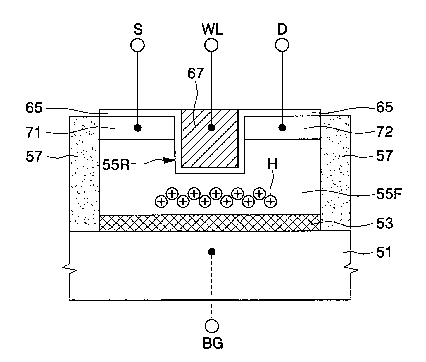
The present invention provides a type of DRAM cell that includes a single transistor and a recess channel. The transistor has a source, drain, and a floating body between them. The recess channel has a gate electrode inside it. The DRAM cell has an isolation layer and an integrated circuit substrate. The technical effects of this invention include improved performance and reliability of the DRAM cells, as well as simplified fabrication processes.

Problems solved by technology

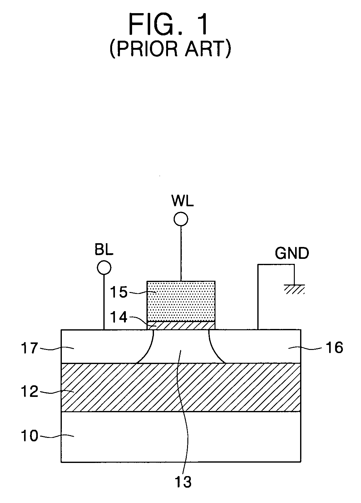
However, as electronic products using semiconductor devices are being made increasingly thin, light-weight, and compact, it has generally become necessary to highly integrate DRAMs.
However, techniques for highly integrating the DRAMs are faced with several limits.
However, reduction of the size of the capacitor generally causes a decrease in capacitance.
Reducing the thickness of the capacitor dielectric layer to increase the capacitance may result in leakage current.
In addition, the overlapping region may be extended to increase capacitance, but this technique generally increases the difficulty of certain processes, such as a process for increasing an aspect ratio.
The DIBL typically makes it difficult to control a drain current by means of the threshold voltage.
As a result, the reduction of the channel length may make it difficult to turn off the transistor.
That is, the short channel effect may make it difficult to store and read data in the single transistor floating body DRAM cell.

Method used


Image

  • Methods of fabricating a single transistor floating body DRAM cell having recess channel transistor structure
  • Methods of fabricating a single transistor floating body DRAM cell having recess channel transistor structure
  • Methods of fabricating a single transistor floating body DRAM cell having recess channel transistor structure

Examples


Embodiment Construction

[0029]The invention is described more fully hereinafter with reference to the accompanying drawings, in which embodiments of the invention are shown. This invention may, however, be embodied in many different forms and should not be construed as limited to the embodiments set forth herein. Rather, these embodiments are provided so that this disclosure will be thorough and complete, and will fully convey the scope of the invention to those skilled in the art. In the drawings, the size and relative sizes of layers and regions may be exaggerated for clarity.

[0030]It will be understood that when an element or layer is referred to as being “on”, “connected to” or “coupled to” another element or layer, it can be directly on, connected or coupled to the other element or layer or intervening elements or layers may be present. In contrast, when an element is referred to as being “directly on,”“directly connected to” or “directly coupled to” another element or layer, there are no intervening ...


PUM


Abstract

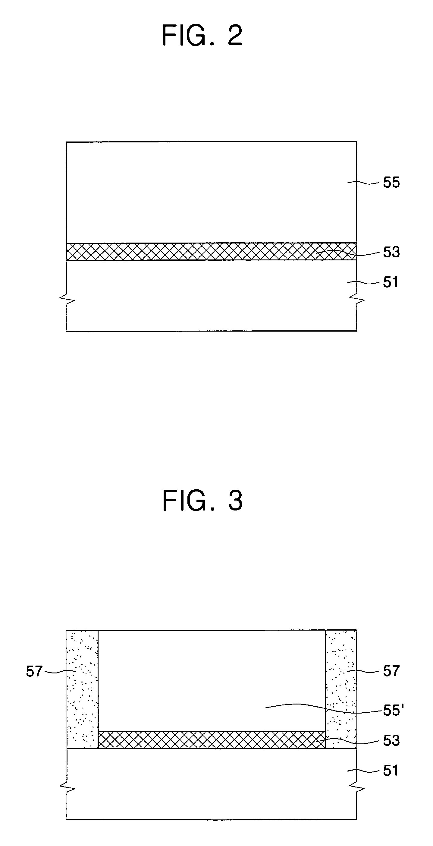
Methods of fabricating a single transistor floating body dynamic random access memory (DRAM) cell include forming a barrier layer on a semiconductor substrate. A body layer is formed on the barrier layer. An isolation layer is formed defining a floating body region within the body layer. A recess region is formed in the floating body region. A gate electrode is formed in the recess region. Impurity ions of a first conductivity type are implanted into a portion of the floating body region on a first side of the recess region to define a source region and into a portion of the floating body on an opposite side of the recess region to define a drain region to provide a floating body.

Description

CROSS-REFERENCE TO RELATED APPLICATION[0001]This application is related to and claims priority from Korean Patent Application No. 2005-0027239, filed Mar. 31, 2005, the contents of which are hereby incorporated herein by reference in their entirety.BACKGROUND OF THE INVENTION[0002]The present invention relates to semiconductor devices and methods of fabricating the same, and more particularly, to single transistor floating body dynamic random access memory (DRAM) cells having a recess channel transistor structure and methods of fabricating the same.[0003]A dynamic random access memory (DRAM) is one kind of volatile memory device. A DRAM has a plurality of DRAM cells storing digital data, i.e., “0”s and “1”s. A structure using one capacitor, one transistor, and interconnections to implement the DRAM cell is widely employed. However, as electronic products using semiconductor devices are being made increasingly thin, light-weight, and compact, it has generally become necessary to high...

Claims


Application Information

Patent Timeline
Patent Type & Authority Patents(United States)
IPC IPC(8): H01L21/336H10B12/00H10B10/00
CPCH01L27/108H01L27/10802H01L29/7841H01L29/78648H10B12/20H10B12/00H01L21/18H10B99/00
Inventor HUO, ZONG-LIANGBAIK, SEUNG-JAEYEO, IN-SEOKYOON, HONG-SIKKIM, SHI-EUN
Owner SAMSUNG ELECTRONICS CO LTD
Learn More