
Bumper/muffler assembly

a technology of bumper/muffler and assembly, which is applied in the direction of bumpers, machines/engines, vehicular safety arrangements, etc., can solve the problems of inability to meet the needs of vehicles, etc., to achieve the effect of improving the bumper/muffler assembly, less expensive, and high impact load

Inactive Publication Date: 2008-02-05
OCV INTELLECTUAL CAPITAL LLC
View PDF28 Cites 24 Cited by
  • Summary
  • Abstract
  • Description
  • Claims
  • Application Information

AI Technical Summary

Benefits of technology

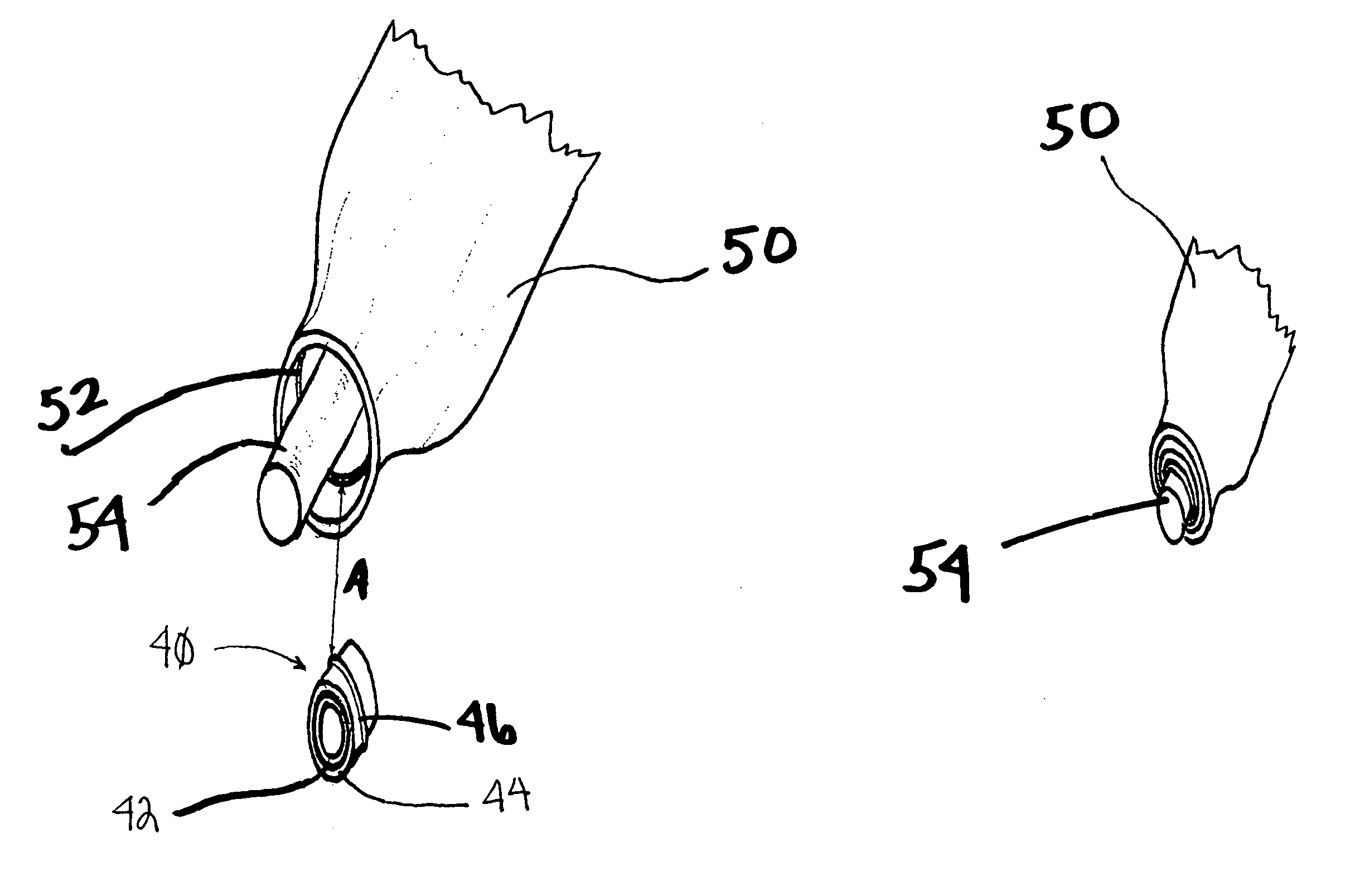
[0012]These needs are met by the present invention, wherein improved bumper / muffler assemblies are provided. In these assemblies, the muffler outer shell may be formed from a lightweight metal or a composite material. Such materials are typically less expensive than thicker metals designed to also absorb high impact loads. Composite outer shells are further advantageous as tooling costs for such parts are typically lower than for metal parts. Furthermore, composite outer shells can be more easily designed and formed into intricate shapes and sizes so as to be received in irregularly shaped vehicle recesses and cavities.
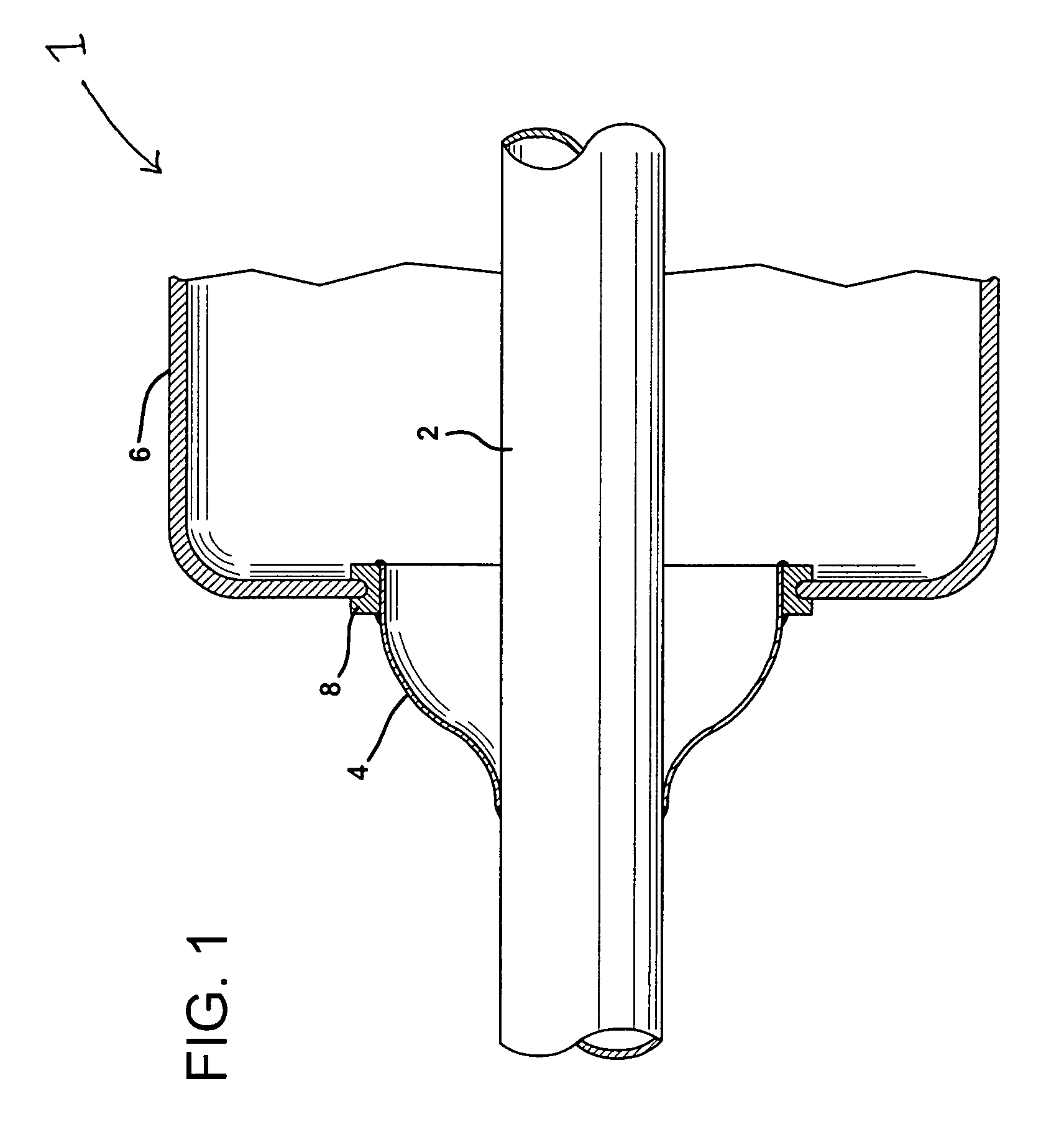
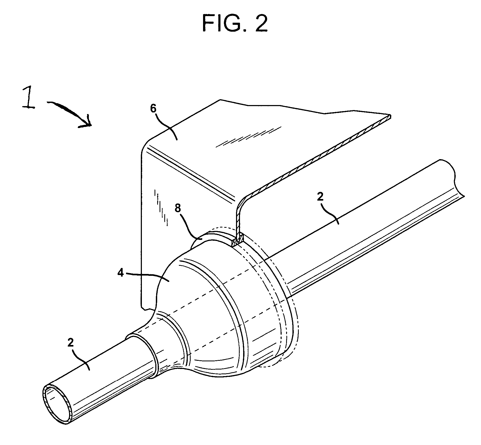
[0017]The bumper may comprise a main body having front, rear, upper and lower surfaces. The front surface faces away from a vehicle. The rear surface faces toward the vehicle. The upper surface faces away from ground and the lower surface faces toward ground. The main body further includes a recess formed in the rear surface and one of the upper or lower surfaces for receiving the muffler shell such that the main body provides impact protection for the muffler shell. A portion of the main body may define at least a part of an outer shell of the muffler.
[0020]In one embodiment, the composite muffler shell is designed so that the distance from the centerline of the exhaust pipe to the muffler shell is longer in the middle than at either end of the muffler. This allows flexibility in the composite muffler shell to adjust to differences in the amount of linear expansion / contraction the exhaust pipe undergoes during operation.

Problems solved by technology

If, after a certain period of vehicle operation, the muffler becomes defective and must be replaced, those defective parts must be replaced with costly parts capable of performing dual functions—attenuate acoustic energy and absorb high impact loads.
There are inherent limitations from a design standpoint regarding possible shapes and sizes for metal mufflers.
Hence, the ability to design mufflers capable of being received in irregularly shaped vehicle recesses or cavities is restricted.
It is also noted that the tooling costs for metal mufflers is very high, which is problematic where only a limited number of mufflers are to be produced, e.g., less than 100,000.

Method used


Image

  • Bumper/muffler assembly
  • Bumper/muffler assembly
  • Bumper/muffler assembly

Examples


Embodiment Construction

[0030]The present invention is directed to a muffler, which is associated with a vehicle bumper. For example, the muffler may be mounted to a vehicle bumper, preferably on the backside of a rear bumper (i.e., between the bumper and the car body), such that the muffler is protected from impact damage by the bumper and also by virtue of it not being a part of the vehicle with the least or nearly least clearance from the ground. Because the muffler is not subjected to high impact loads, the shell of the muffler can be formed from materials that do not have high impact resistant properties, such as some phenolic resins, examples noted below, and thin metals, e.g., stainless steels having a thickness less than about 1.5 mm. Further, the muffler may be longer than conventional mufflers, e.g., it may have a length up to almost the length of the bumper, e.g., greater than 60 inches, such that the muffler operates more efficiently, especially in dissipating low frequency acoustic energy.

[003...


PUM


Abstract

A bumper / muffler assembly is provided comprising a bumper; and a muffler having an outer shell. The outer shell may be formed from a non-high impact resistant material, such as a thin metal or a composite material. The muffler may comprise a separate element from the bumper, which is coupled thereto, or is formed as an integral part of the bumper.

Description

RELATED APPLICATIONS[0001]This application claims the priority of and is a continuation-in-part of U.S. Ser. No. 09 / 992,254 (Issued as U.S. Pat. No. 6,668,972) filed Nov. 6, 2001, entitled BUMPER / MUFFLER ASSEMBLY, by Norman Thomas Huff et al., the disclosure of which is incorporated herein by reference in its entirety.TECHNICAL FIELD AND INDUSTRIAL APPLICABILITY OF THE INVENTION[0002]This invention relates to a bumper / muffler assembly wherein a muffler, preferably made from a composite material, is associated with a vehicle bumper.BACKGROUND OF THE INVENTION[0003]U.S. Pat. No. 5,726,398 to Zahn et al. discloses a bumper / muffler assembly. A portion of the structure defining the muffler also forms part of the bumper and, hence, must be capable of absorbing high impact loads. If, after a certain period of vehicle operation, the muffler becomes defective and must be replaced, those defective parts must be replaced with costly parts capable of performing dual functions—attenuate acoustic...

Claims


Application Information

Patent Timeline
Patent Type & Authority Patents(United States)
IPC IPC(8): F16F15/02F01N1/10F01N7/16B60R19/18B60R19/48F01N1/00F01N1/04F01N1/24F01N13/16F01N13/18
CPCB60R19/48F01N1/003F01N13/16F01N13/18F01N13/1838F01N13/1888B60R2019/1813B60R2019/1833F01N2310/02F01N2310/04
Inventor HUFF, NORMAN T.SANDERS, ANDREW W.CLEMENTS, CHRISTOPHER J.WIEMANN, JUERGENTOMASZEWSKI, RONALDCHAMPNEY, LARRY J.CRAWLEY, ROBERT L.
Owner OCV INTELLECTUAL CAPITAL LLC
Learn More