
Ink jet printing apparatus

a printing apparatus and jet printing technology, applied in printing and other directions, can solve the problems of deteriorating printing quality, affecting printing quality, and affecting printing quality, so as to prevent or suppress the generation of reaction products and achieve stable printing quality.

Inactive Publication Date: 2008-01-01
CANON KK
View PDF9 Cites 9 Cited by
  • Summary
  • Abstract
  • Description
  • Claims
  • Application Information

AI Technical Summary

Benefits of technology

[0016]To resolve the above described problems, the present invention provides an ink jet printing apparatus that prevents or suppresses the generation of a reaction product by a reaction liquid (a liquid composition) and ink on a face surface, and that removes the ink, the reaction liquid and the reaction product attached to the face surface, so that a stable printing quality can be maintained.
[0017]The present invention also provides an ink jet printing apparatus that can prevent ink and a reaction liquid from generating a reaction product that will coagulate near discharge ports, and that can reduce any deviation in the direction of an ink discharge.
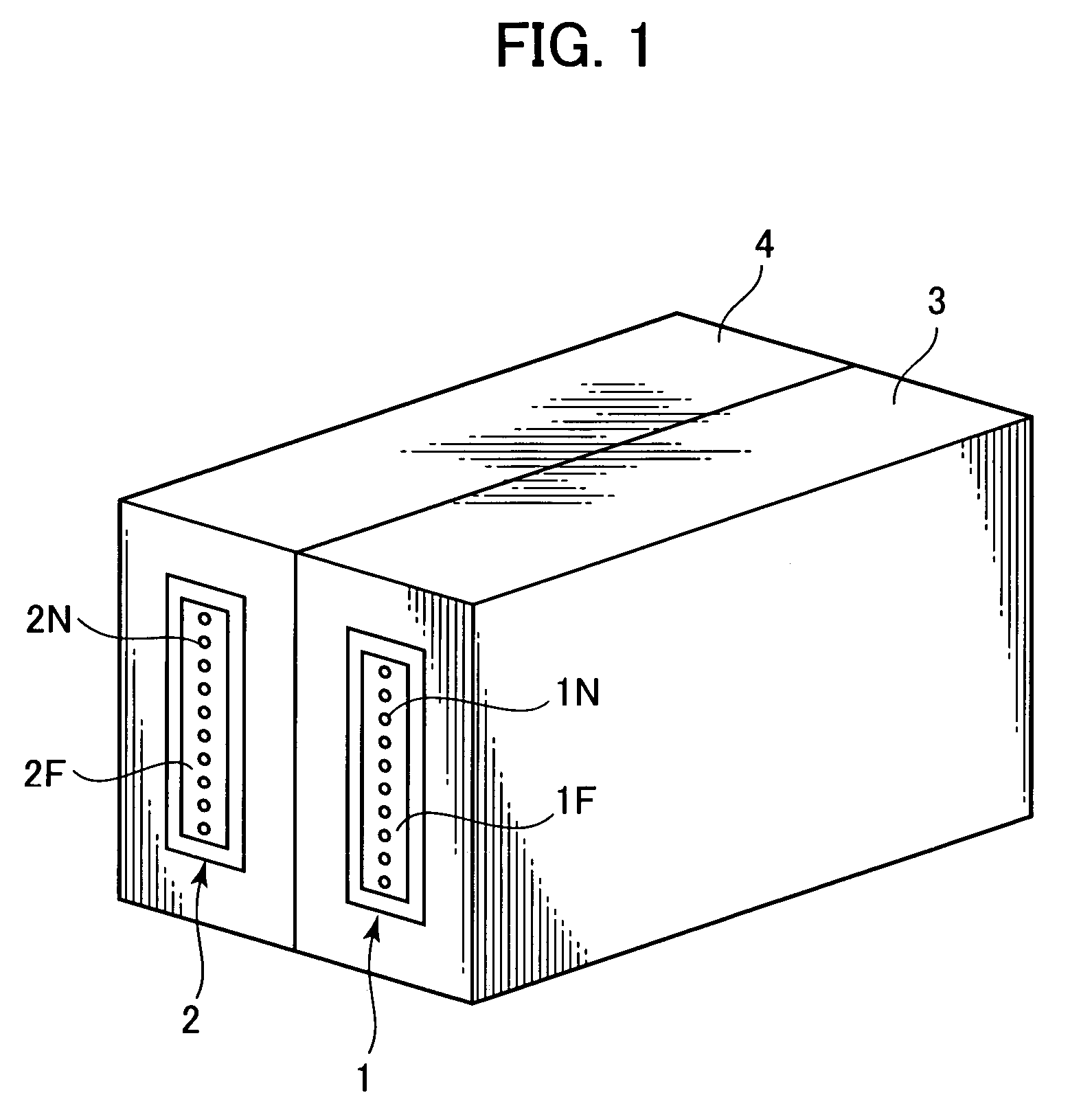
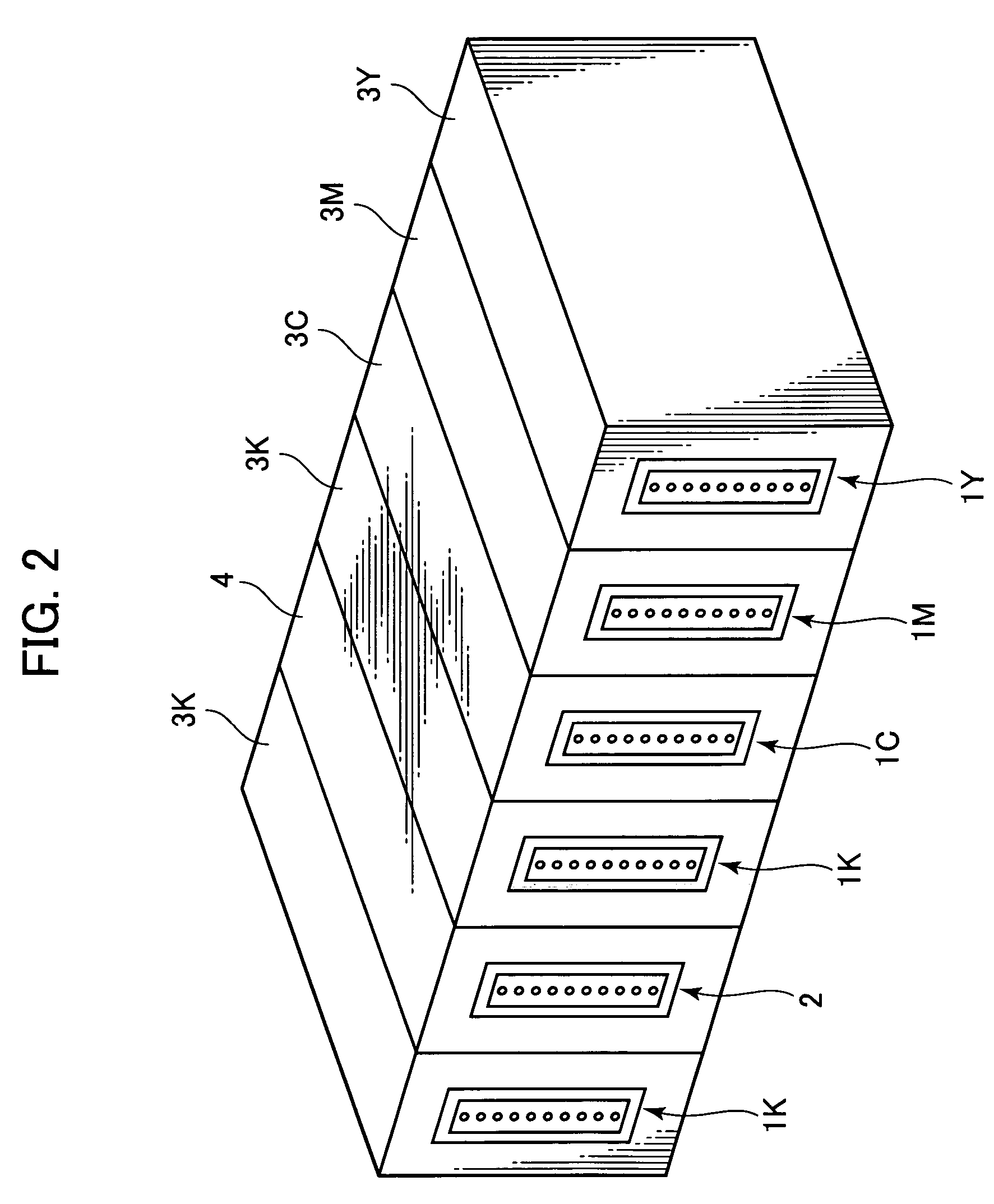
[0020]With this arrangement, since the printing operation is performed by using a discharge head to which the liquid (an anti-coagulation liquid) is applied in advance to prevent or suppress the generation of a reaction product by a reaction of the ink with the reaction liquid, the generation of a reaction product and the attachment of the reaction product to the face surface can be prevented or suppressed, even when, during the discharge of ink, a floating mist comprising the reaction liquid and the ink is produced and is attached to the discharge face (face surface) of the discharge head. Further, even when the reaction product is generated on or attached to the face surface, the reaction product cannot easily coagulate. Therefore, there is little contamination of the discharge faces, and a reaction product attached to the discharge ports can be easily removed.

Problems solved by technology

Furthermore, ink could be attached around the reaction product on the face surface, until it reaches the discharge port, so that a discharge failure or the deflection of the discharge direction could occur.
Due to a discharge failure, for example, the deterioration of printing quality could occur.
Furthermore, the above described problems could also be caused by ink and reaction liquid that leak from a discharge port.
However, this method is not effective for a coagulated product generated by the reaction of ink with a reaction liquid.
However, this method is not considered adequate for the removal of a reaction product coagulated on a face surface.
However, since once the product has coagulated on the face surface it can not easily be dissolved, even after the liquid solvent has been applied and the wiping has been performed, traces of the product remain.
As is described above, for an ink jet printing apparatus employing a reaction liquid and ink, since the coagulated reaction product on the face surface is comparatively strong, the product cannot be fully removed by applying the liquid solution, and traces will remain on the face surface.
As a result, attaining a satisfactory discharge is difficult.
Especially after wiping has been completed, the reaction product may be spread out and remain as a stain on the face surface, and removing such a stain is more difficult.
Further, once the reaction product has been generated, even though it can be easily removed by applying the liquid solution, a wiping operation for scraping off the reaction product is still required.
When this processing is performed repeatedly, each time the printing of a predetermined amount of data is performed, the period required for the processing of all the print data is extended, and this is a problem that is exacerbated by the printing speed.
Furthermore, since an operation for scraping off the thus generated reaction product is performed using a comparatively hard blade and a force that exceeds that required for removing ink, scratching of the face surface tends to occur.
And damage to the face surface is a factor that tends to reduce the durability of an ink jet head.
Especially, the number of times the suction recovery operation is performed is increased, and exceeds that required for an apparatus that employs only ink, i.e., the amount of ink consumed at times other than during printing is increased, which is very uneconomical.

Method used


Image

  • Ink jet printing apparatus
  • Ink jet printing apparatus
  • Ink jet printing apparatus

Examples


first embodiment

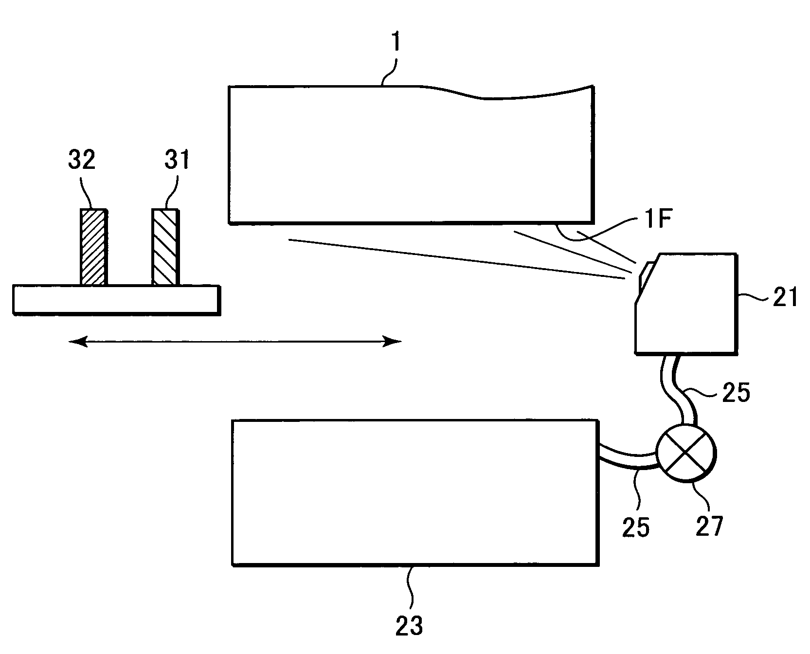
[0062]FIG. 7 is a specific diagram showing a discharge recovery arrangement according to a first embodiment of the present invention.

[0063]In FIG. 7, a spray device 21 is used to spray one of the anti-coagulation liquids in Table 1 on the face surface of the ink head 1, and an anti-coagulation liquid tank 23 is used to retain the anti-coagulation liquid. The anti-coagulation liquid retained in the anti-coagulation liquid tank 23 is supplied by a pump 27, through a supply pipe 25, to the spray 21. The anti-coagulation liquid, sprayed on the face surface by the spray 21, is mixed with ink or reaction liquid that later will be attached to the face surface, and acts to prevent or suppress the generation of a reaction product. Further, the thus applied anti-coagulation liquid also acts to prevent a reaction product, which is generated on or attached to the face surface, from coagulating on the face surface.

[0064]In this embodiment, the above-described tank 23, the pump 27 and the spray d...

second embodiment

[0104]FIG. 9 is a specific diagram showing a structure according to a second embodiment of the present invention for applying an anti-coagulation liquid.

[0105]A core 28 having a comparatively large capillary attraction force is arranged in an anti-coagulation liquid tank 23 and partially projected therefrom. An air hole 26 communicating with the atmosphere is also formed in the tank 23. That is, an anti-coagulation liquid permeates the entire core 28 using capillary attraction. And one end of the core 28 is positioned outside the printing area of an ink head 1 and within the range wherein the ink head 1 is moved, so that the end can rub against the face surface of the ink head 1. With this arrangement, not only can the anti-coagulation liquid be easily applied to the face surface, but also a stain, which could not be removed from the face surface by wiping performed after the preceding recording operation, can be scraped off by the rubbing operation.

[0106]In this case, while taking ...

third embodiment

[0114]According to this invention, in order to prevent or suppress the generation of a reaction product, the anti-coagulation liquid is applied to the face surface of the ink head immediately before the recording operation is initiated. However, when the discharge port area is wet, this liquid tends to change the ink or reaction liquid discharge direction, i.e., it is possible that “deflection” will occur. Therefore, in this embodiment, on the face surface of the ink head, the wetting differs between the discharge port area and the other areas, and water repellency is increased only in the discharge port area. With this arrangement, the anti-coagulation liquid is applied to the face surface, except for the discharge port area, and the ink or reaction liquid discharge direction is not adversely affected by the anti-coagulation liquid.

[0115]Since the discharge port area is highly water repellent, even though the anti-coagulation liquid has not been applied, it is difficult for splashe...


PUM


Abstract

An ink jet printing apparatus can prevent or suppress the generation, by a reaction liquid and ink, of a reaction product on the face surface of a discharge head, and can remove the ink, the reaction liquid or the reaction product adhering to the face surface so as to constantly maintain a stable printing quality. Immediately before a printing operation is initiated, an anti-coagulation liquid is sprayed on the face surface of a discharge head, and the discharge head performs the discharge operation (printing operation) with the anti-coagulation liquid applied to the face surface. When the printing operation has been completed, or when the printing of a predetermined amount of data has been performed, the face surface of the discharge head is wiped by blades to remove the ink and the reaction liquid. Since the anti-coagulation liquid is applied to the face surface in advance, the generation of the reaction product on the face surface is prevented or suppressed. Furthermore, even when a reaction product is adhered to the face surface, the coagulation of this product on the face surface can be prevented.

Description

BACKGROUND OF THE INVENTION[0001]1. Field of the Invention[0002]The present invention relates to an ink jet printing apparatus, and, in particular, to an ink jet printing apparatus that performs printing by discharging, onto a recording medium, an ink and a liquid composition that renders a coloring material in the ink insoluble or flocculated.[0003]2. Description of the Related Art[0004]Conventionally, it is well-known that, for an ink jet printing apparatus, a liquid compound (hereinafter also referred to as a “reaction liquid”) that reacts with ink, rendering the coloring material in the ink insoluble or flocculated, is employed in order, for example, to improve water repellency, durability and the development of color on a printed image.[0005]Sometimes, however, with such an ink jet printing apparatus, tiny floating droplets, constituent components of a mist generated when ink and a reaction liquid are discharged from an ink jet head, are attached to and coagulate on a surface i...

Claims


Application Information

Patent Timeline
Patent Type & Authority Patents(United States)
IPC IPC(8): B41J2/135B41J2/165B41J2/01B41J2/015
CPCB41J2/16552B41J2/1623B41J2/1631B41J2/1639B41J2/1645B41J2/16538
Inventor YAMAGUCHI, NOBUHITONAKAZAWA, KOICHIRO
Owner CANON KK
Learn More