
Image forming method and image forming apparatus

a technology of image forming and forming method, which is applied in the direction of electrographic process apparatus, instruments, optics, etc., can solve the problems of difficult for human eyes to distinguish yellow from white, yellow printed on a white recording medium,

Active Publication Date: 2005-06-09
KYOCERA DOCUMENT SOLUTIONS INC
View PDF1 Cites 2 Cited by
  • Summary
  • Abstract
  • Description
  • Claims
  • Application Information

AI Technical Summary

Benefits of technology

[0010] The present invention was made in light of the problems mentioned above, and the object of the invention is to provide a method and apparatus of forming image, with which, when cleaning the transfer belt, the transfer belt is cleaned well enough and flaws can not be perceived by human eyes in transferred images even if scratches are produced due to entrainment of foreign matter.
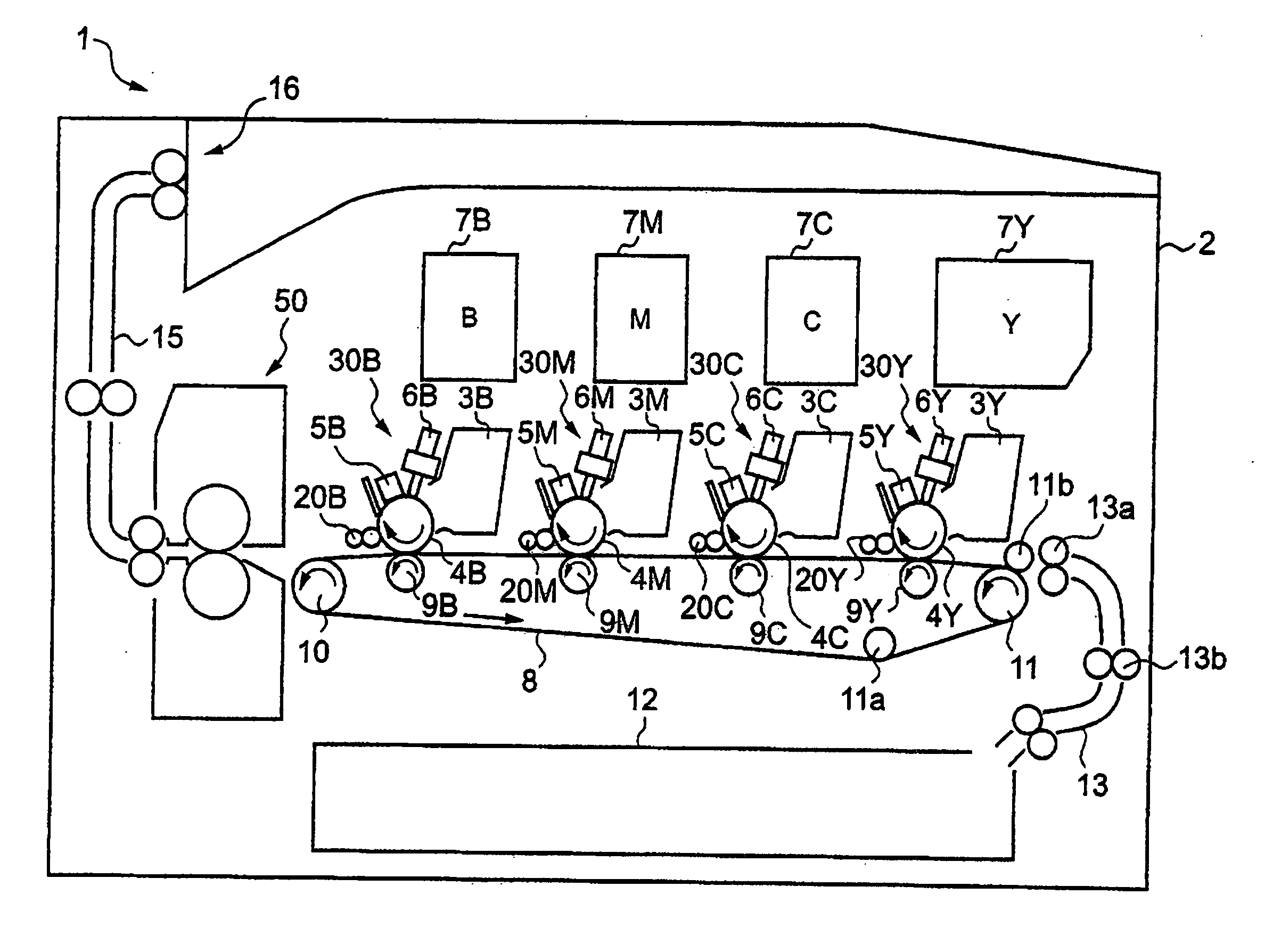
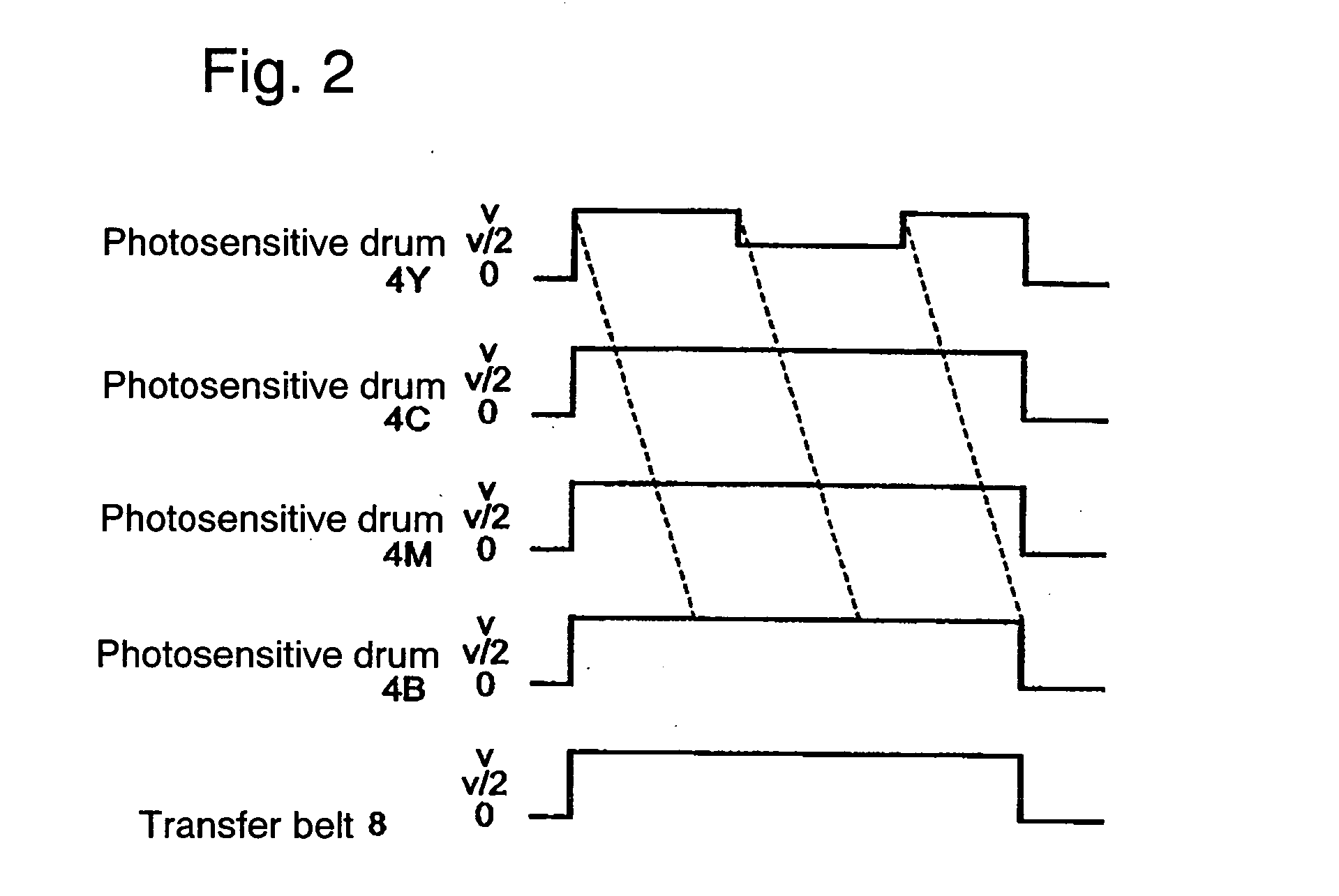
[0014] The present invention is made on the basis of the knowledge mentioned above. The first substance of the present invention is to apply bias voltage of reverse polarity to at least one of the primary transfer rollers 9Y˜9B, to allow the velocity difference between the peripheral velocity of the photosensitive drum 4Y on which a toner image difficult to be discerned when printed on a white recording medium (recording medium having high spectroreflectivity in the range of wave length of visible light), concretively toner image having spectroreflectivity relatively like white that has about 100% specroreflectivity all over the range of wave length of visible light compared to other colors is to be formed and the transfer velocity of the transfer belt 8 or intermediate transfer belt 8a to be increased to a value larger than a predetermined value, and to allow the peripheral velocity of the photosensitive drum 4B on which toner image of which spectroreflectivity is the lowest is to be formed to be controlled at about the same as the transfer velocity of the transfer belt 8 or intermediate transfer belt 8a (the first velocity control), when cleaning off the toner remaining on the transfer belt 8 or intermediate transfer belt 8a shown in FIG. 1 or FIG. 5 in order to perform cleaning of the transfer belt 8 or intermediate transfer belt 8a well enough.
[0015] The second substance of the present invention is to apply bias voltage of reverse polarity to at least one of the primary transfer rollers 9Y˜9B, to allow the velocity difference between the peripheral velocity of the photosensitive drum 4Y on which toner image of which spectroreflectivity is the highest is to be formed and the transfer velocity of the transfer belt 8 or intermediate transfer belt 8a to be increased to a value larger than a predetermined value, and to allow the photo sensitive drum 4B on which toner image having the lowest spectroreflectivity is to be formed to be detached from the transfer belt 8 or intermediate transfer belt 8a, when cleaning off the toner remaining on the transfer belt 8 or intermediate transfer belt 8a shown in FIG. 1 or FIG. 5 in order to perform cleaning of the transfer belt 8 or intermediate transfer belt 8a well enough.
[0020] The present invention proposes an image forming apparatus provided with a plurality of image forming units having image carrying bodies for carrying toner images of several colors, the image forming units being arranged along a transfer body for transferring recording medium, and a plurality of image transfer means each faces each of said image carrying body across said image transfer body pinching the image transfer body, wherein are provided a reverse bias applying means for applying the bias voltage opposite in polarity to that applied to when the image on the image carrying body is transferred to the recording medium to at least one of the transfer means, preferably to the transfer means corresponding to the image carrying body on which a toner image of which the spectroreflectivity at wavelength of 550 nm is the highest is to be formed, and a control means which can perform speed control of a first speed control mode for controlling the peripheral velocity of an image carrying body of highest spectroreflectivity to be different from the transfer velocity of said transfer body when cleaning off the toner remaining on said transfer body.
[0026] As has been mentioned in the forgoing, according to the present invention, even if scratches are produced on the image carrying body on which a toner image of which the spectroreflectivity at wavelength of 550 nm is the highest is to be formed, the image transferred to recording medium is not perceived to have a flaw, for the image formed with the toner of highest spectroreflectivity is difficult for human eyes to discern. Therefore, the invention bring about effect that not only the transfer body can be fully cleaned but flaws do not appear practically in transferred images even if scratches are produced due to entrainment of foreign matter.
[0027] Further, in the present invention, as the second control mode by which the peripheral velocities of all the image carrying bodies are controlled to be about the same as the transfer velocity of the transfer body before performing the first control mode when cleaning off the toner remaining on the transfer body, foreign matter adhered electrostatically to the transfer body is reversely transferred to any one of the image carrying bodies, and generation of scratches can be prevented or suppressed to a minimum when shifted to the first control mode.

Problems solved by technology

Therefore, it is difficult for human eyes to distinguish yellow from white when yellow is printed on a white recoding medium.
Therefore, yellow printed on a white recording medium is difficult to discern for human eyes.

Method used


Image

  • Image forming method and image forming apparatus
  • Image forming method and image forming apparatus
  • Image forming method and image forming apparatus

Examples


Embodiment Construction

[0035] A preferred embodiment of the present invention will now be detailed with reference to the accompanying drawings. It is intended, however, that unless particularly specified, dimensions, materials, relative positions and so forth of the constituent parts in the embodiments shall be interpreted as illustrative only not as limitative of the scope of the present invention.

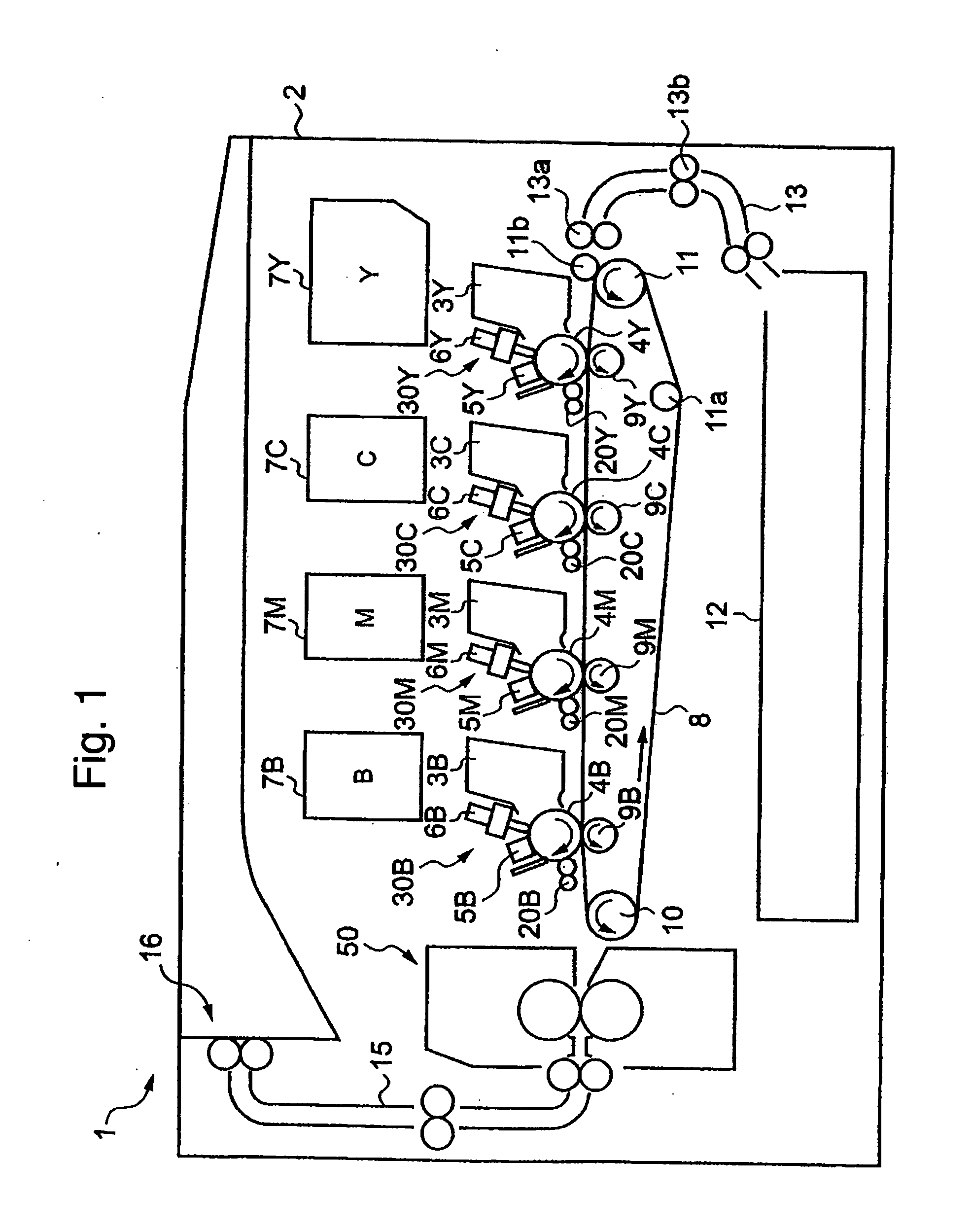
[0036]FIG. 1 is a schematic representation of an example of direct tandem type color printer used as a image forming apparatus. In the printer 1, a full-color image output or mono-color image output is selected depending on the color information of original image data sent from an external computer(not shown in the drawing). A sheet transfer belt 8 (intermediate transfer belt) made of poly-vinylidene-fluoride (PVDF) for example is provided in the housing 2 of the printer 1 for transferring sheet papers, the sheet transfer belt 8 is looped over a driving roller 10, a follower roller 11, and an opposite-side rol...


PUM


Abstract

An image transfer method and apparatus are provided, with which, even if scratches are produced due to entrainment of foreign matter on the surface of the image carrying body on which a toner image of which the spectroreflectivity at wavelength of 550 nm is the highest is to be formed, the image transferred to a recording medium is not perceived to have a flaw, for the image formed with the toner of which the spectroreflectivity at wavelength of 550 nm is the highest is difficult for human eyes to discern when it is printed on a white recording medium. When cleaning off the toner remaining on the sheet transfer belt 8 or intermediate transfer belt 8a, reverse bias voltage is applied to at least one of the transfer rollers 9Y˜9B, the peripheral velocity of the photosensitive drum 4Y on which a yellow toner image of which the spectroreflectivity at wavelength of 550 nm is the highest is to be formed is allowed to be different from the transfer velocity of the sheet transfer belt 8 or intermediate transfer belt 8a, and at least the photosensitive drum 4Y on which said yellow toner image of which the spectroreflectivity at wavelength of 550 nm is the highest is to be formed is detached from the sheet transfer belt 8 or intermediate transfer belt 8a.

Description

BACKGROUND OF THE INVENTION [0001] 1. Field of the Invention [0002] The present invention is related to an image forming method in a copying machine, printer, facsimile machine, etc. and an apparatus using the method, particularly to a color image forming method of tandem type and an apparatus using the method. [0003] 2. Description of the Related Art [0004] Generally, there is a full-color image forming apparatus using an intermediate image transfer belt (intermediate transfer body) composed such that toner images are superimposed sequentially on the intermediate transfer belt (primary image transferring) to form a color image, then the color image on the intermediate image transfer belt is transferred to a recording medium(recording sheet paper, hereafter referred to as a sheet paper) at a secondary image transferring position to obtain a sheet paper with the color image formed thereon. This kind of color image forming apparatus is called an intermediate tandem type image forming ...

Claims


Application Information

Patent Timeline
Patent Type & Authority Applications(United States)
IPC IPC(8): G03G15/16
CPCG03G15/168
Inventor YAMANE, SHINJIWATANABE, TAKESHIMATAYOSHI, AKIRAOTA, KATSUYA
Owner KYOCERA DOCUMENT SOLUTIONS INC
Learn More