
System and method for linking a plurality of network switches

a network switch and network switch technology, applied in the field of computer networks, can solve the problems of limited expansion of san fabric networks, inability to implement san fabric channels, and inability to meet the requirements of wide area network (“wan”)/lan applications, etc., and achieves the effects of minimal or no downtime, easy maintenance, and easy upgrad

Inactive Publication Date: 2007-12-11
SAICO INFORMATION TECH WUHAN
View PDF158 Cites 33 Cited by
  • Summary
  • Abstract
  • Description
  • Claims
  • Application Information

AI Technical Summary

Benefits of technology

[0012]The invention overcomes the above-identified problems as well as other shortcomings and deficiencies of existing technologies by providing a storage network device that performs a multiplicity of functions and has a multiplicity of port types to allow it to connect to a variety of network types (e.g., Fibre Channel, Gigabit Ethernet, etc.) and is easily maintainable and / or can be easily upgraded with either minimal or no downtime.
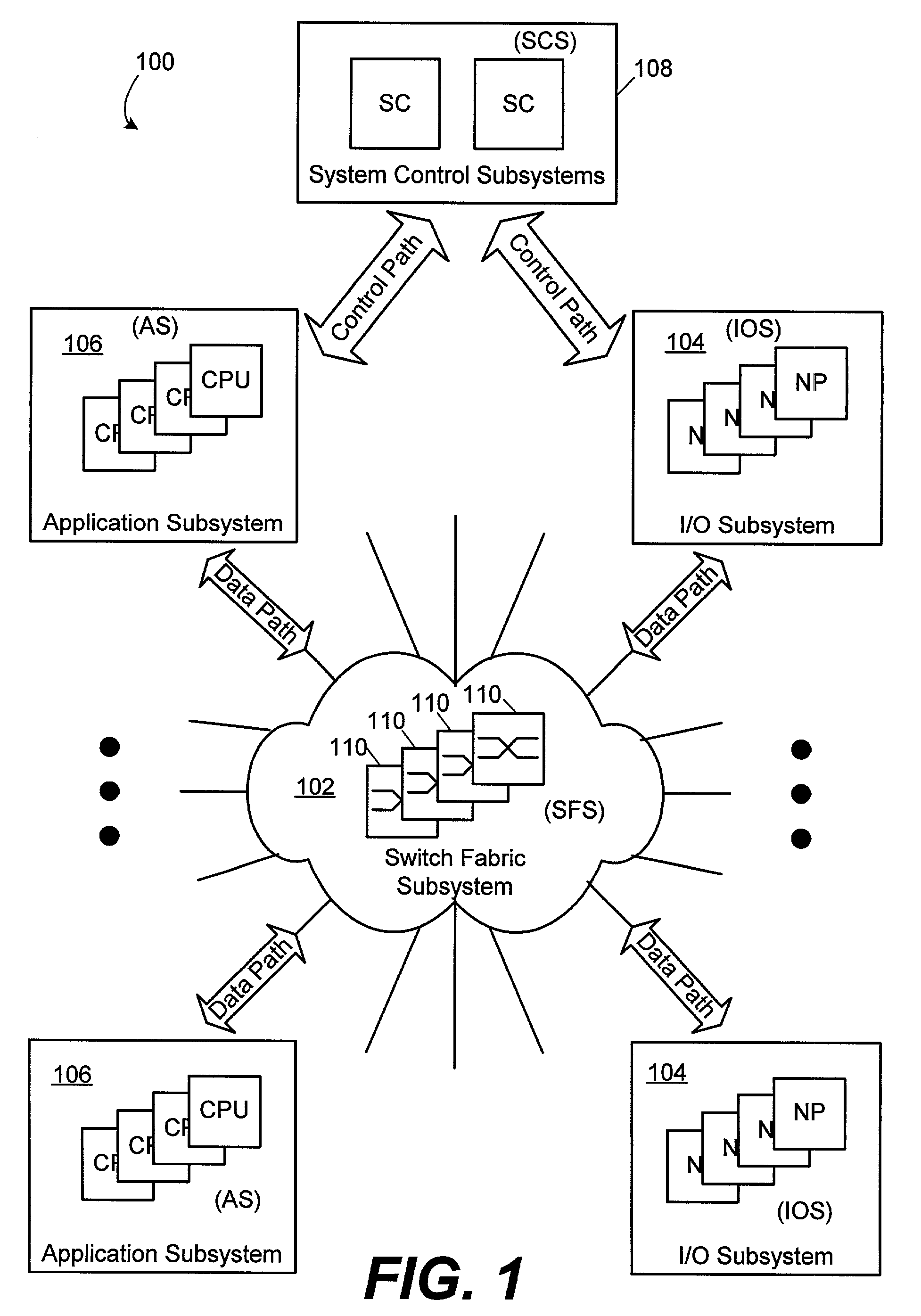
[0014]The Switch Fabric Subsystem is a protocol agnostic cell or packet switching infrastructure that provides the high performance and highly scalable interconnections between the I / O Subsystems and Application Subsystems. It provides primary data paths for network traffic being moved by the switch. The I / O Subsystems provide the actual port connectivity to the external network devices that use the switch to communicate with other external network devices. The I / O Subsystems are part of the data path and are responsible for making the high performance, low level decoding of ingress frames from the external ports; and switching / routing, identifying the destination I / O subsystem for the frame, and queuing the frame for transmission through the Switching Fabric. The I / O Subsystems process packets at the very lowest protocol levels (Data Link and Network Layer of the OSI Model) where fast switching and routing decisions can be made. The Application Subsystems provide the platforms for higher level processing of frames and data streams in the switch system. The Application Subsystems have more advanced programmability and functionality than the I / O Subsystems, but rely on the control and data information provided by the I / O Subsystems to maintain high performance packet throughput. Typical applications that can run on the Application Subsystems are caching, storage virtualization, file serving, and high level protocol conversion. The System Control Subsystems provide the overall management of the storage network switch. Most of the low level switching and routing protocol functions are executed on the System Control Subsystems. In addition, management access functions such as the SNMP agent, web server, telnet server, and the direct command line interface reside on the System Control Subsystems. The hardware and software executing on the System Control Subsystems are responsible for managing the other subsystems in the network storage switch.

Problems solved by technology

Expansion of SAN fabric networks is limited in that conventional SAN fabric channels cannot be implemented over geographically distant locations.
Conventional Fibre Channel architecture is not suitable for wide area network (“WAN”) / LAN applications.
While SCSI and Ethernet may be used to implement a WAN / LAN, these two protocols are not efficient for storage applications.
Interconnecting heterogeneous SANs that may be easily scaled upward using these translation bridges is very difficult because the translation bridges usually become the bottleneck in speed of data transfer when the clients (servers and / or storage devices) become larger in number.
In addition, in a mixed protocol environment and when the number of different protocols increase, the complexity of the software installed on the translation bridges increases, which further impacts performance.
A limitation of the size of SAN fabric networks, in terms of storage capacity, is cost and manpower.
Another major, if not primary, expense is the cost of managing a SAN.
SAN management requires a lot of manpower for maintenance and planning.
For example, as storage capacity grows, issues such as determining server access to storage devices, backup strategy, data replication, data recovery, and other considerations become more complex.
However, the user has to power down the existing system and reconnect the new chassis into the existing system.
Unfortunately, this upgrade causes system downtime and potential loss of revenue.
Switches have a limited resource—the switch fabric or routing core.
The problem with existing switches is that the internal switch fabric is fixed in size.
This is a disruptive upgrade that causes all nodes connected to the switch to lose connectivity while the upgrade is occurring.
However, these interconnects can become congested and limit the throughput of the network.
Unfortunately, to achieve a non-blocking switch in a typical configuration half of the ports on the switch are then used for interconnect purposes.
As every switch system is internally limited to a specific amount of devices that can be coupled with each switch such an interconnection is not desirable.
These couplings are, however, limited in their flexibility as their assignment to the plurality of channels of each switch is static and, thus, not very flexible.
It is, therefore, highly likely that traffic within the switch system will be blocked due to an already in-use trunk coupling.

Method used


Image

  • System and method for linking a plurality of network switches
  • System and method for linking a plurality of network switches
  • System and method for linking a plurality of network switches

Examples


Embodiment Construction

[0033]The present invention is directed to a storage network device that performs a multiplicity of functions and has a multiplicity of port types to allow it to connect to a variety of network types (e.g., Fibre Channel, Gigabit Ethernet, etc.). A primary function of the invention is to act as a storage network switch wherein frames are switched from port to port. However, because of its architecture, the present invention has the ability to perform many additional functions that take advantage of its high performance, highly scalable, and highly programmable infrastructure.

[0034]The following description of the exemplary embodiments of the present invention contains a number of technical terms using abbreviations and / or acronyms which are defined herein and used hereinafter:

[0035]

APApplication ProcessorASApplication SubsystemBMCBuffer Management CoprocessorEMUEnvironmental Monitoring UnitsFCFibre ChannelFCPFabric CoprocessorFIOCFabric I / O ControllerFPFabric ProcessorGb / sgigabits p...


PUM


Abstract

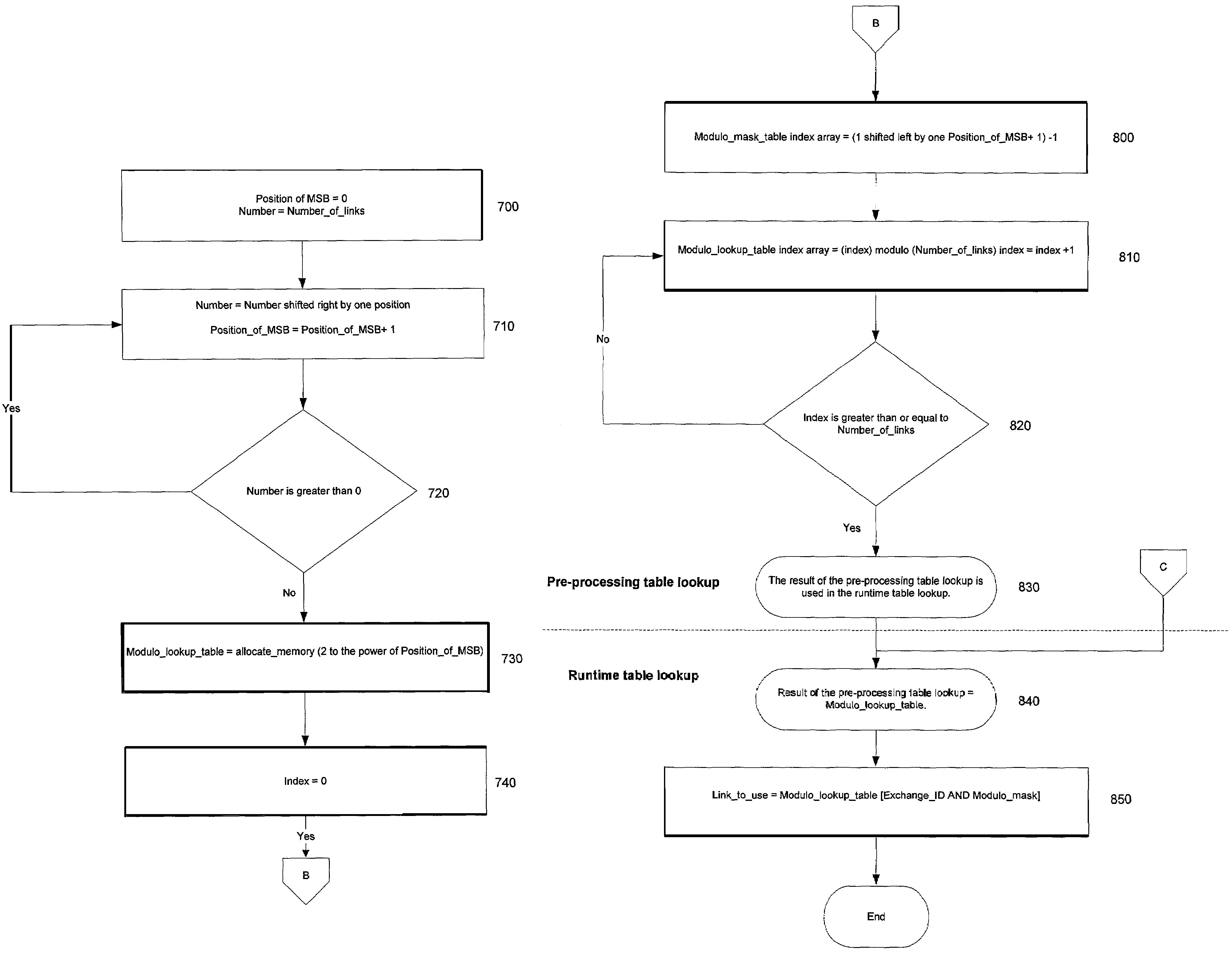
A method of linking at least two network switches is disclosed, wherein each network switch switches data traffic of a plurality of devices, through a plurality of couplings. The method comprises the steps of generating a data stream including an identifier to be sent from a first to a second network switch, generating a number identifying one of the couplings from the identifier, and using the identified coupling for transfer of the data stream.

Description

CROSS-REFERENCE TO RELATED APPLICATIONS[0001]This application is related to U.S. patent application Ser. No. 09 / 738,960 filed on Dec. 14, 2000, now U.S. Pat. No. 6,792,507; U.S. patent application Ser. No. 10 / 015,047 filed on Oct. 26, 2001; U.S. patent application Ser. No. 10 / 039,190 filed on Dec. 31, 2001, now abandoned; U.S. patent application Ser. No. 10 / 039,189 filed on Dec. 31, 2001; and U.S. patent application Ser. No. 10 / 039,184 filed on Dec. 31, 2001, all of which are incorporated herein by reference in its entirety for all purposes. This application is also related to the following four U.S. patent applications which are being filed concurrently herewith: U.S. patent application Ser. No. 10 / 117,040 entitled “System and Method for Expansion of Computer Network Switching System Without Disruption Thereof”; U.S. patent application Ser. No. 10 / 117,266 entitled “System and Method for Guaranteed Link Layer Flow Control”; U.S. patent application Ser. No. 10 / 117,638 entitled “Fibre...

Claims


Application Information

Patent Timeline
IPC IPC(8): H04L12/56
CPCH04L45/00H04L49/552H04L49/45H04L49/357
Inventor IYER, RAM GANESANYAO, HAWKINSWITKOWSKI, MICHAELGUNLOCK, RICHARD
Owner SAICO INFORMATION TECH WUHAN
Learn More