Co-injection nozzle with improved interior layer termination

a technology of injection nozzle and interior layer, which is applied in the direction of dough shaping, combs, buttons, etc., can solve the problems of breaking the interior layer material, the need to end the interior layer of the material flow in a quicker or more abrupt manner, and the barrier property of the bottle can be adversely affected, so as to increase the volume amount of material, increase the control of a volume of material, and increase the volume of material.

Active Publication Date: 2007-12-11
CINCINNATI MILACRON INC
View PDF3 Cites 28 Cited by
  • Summary
  • Abstract
  • Description
  • Claims
  • Application Information

AI Technical Summary

Benefits of technology

[0015]The present invention addresses the above-described limitations of the conventional nozzle assemblies for co-injecting two or more materials into a cavity to form a molded object. The present invention provides an approach to increase the control of a volume of material forming an interior (core) layer of the molded object. The controllability of the volume of interior layer material provided by the methods and assemblies disclosed herein extend the length of a tail section of the interior layer and increase the volume amount of material in the tail section of the interior layer to provide an interior layer that extends from a neck portion to a gate portion of a preform without having the tail of the interior layer extend into the gate portion. Furthermore, the controllability of the volume of interior layer material provided by the present invention benefits other configurations of molded objects, for example a molded object having a five layer construction. Other exemplary configurations include, but are not limited to molded objects formed by offsetting the leading edge of an interior layer material from a velocity gradient in a controlled volume shot. A significant result of this controllability are manufactured objects having improved barrier layer protection which, in turn, extends the shelf life of products contained in such manufactured objects. Thus, the present invention beneficially extends the shelf life of goods and reduces the scrap rate and cost of such goods caused by shelf life expiration.
[0016]In one embodiment of the present invention, a nozzle assembly is disclosed. The nozzle assembly includes a first inlet to receive a first polymeric material and a second inlet to receive a second polymeric material. A first channel of the nozzle assembly has an inner passage to receive a first portion of the first polymeric material from the first inlet and feeds a combination area with the first polymeric material. A second channel of the nozzle assembly has an inner passage to receive a second portion of the first polymeric material from the first inlet and feed the combination area with the first polymeric material. A third channel of the nozzle assembly has an inner passage to receive a portion of the second polymeric material from the second inlet and feed the combination area with the second polymeric material. The combination area simultaneously combines the polymeric materials from the first, second, and third channels to form an annular output stream having multiple annular layers. Additionally, the combination area is configured to terminate formation of an interior layer of the annular output stream after termination of the flow of the second polymeric material from a second material source using a minimum volume of material flowing from the first and second channel while avoiding flow instabilities.

Problems solved by technology

One problem in the field of co-injection molding resides in the need to end an interior layer of the material flow in a quicker or more abrupt manner.
If this region is not free of the interior layer material the next controlled volume shot of material into the mold becomes contaminated with the interior layer material that remains in this region.
As such, intermediate surface layers of conventional nozzles require cleaning, which is burdensome due to the sequential build of material layers.
Absent a barrier layer that extends the entire sidewall length, the barrier property of the bottle can be adversely affected.
This thinning eventually leads to breaking of the interior layer material from the combining element.
The second is more burdensome to detect and can typically be detected by the lack of bonding between the inner and outer layers of material.

Method used


Image

  • Co-injection nozzle with improved interior layer termination
  • Co-injection nozzle with improved interior layer termination
  • Co-injection nozzle with improved interior layer termination

Examples


Embodiment Construction

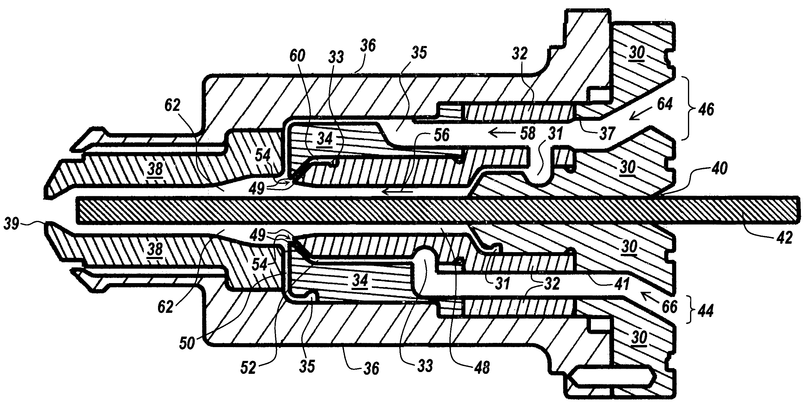
[0032]The ability to quickly end or break the tail of the material forming the interior layer of a molded plastic object leaves a region extending from a stream combination area in a nozzle to a gate of a mold cavity substantially free of the interior layer material to avoid the need to clean any surfaces in this region prior to a subsequent controlled volume shot. The stretching and eventual breaking of the interior layer material are achieved by controlling at least the flow characteristics of the inner and outer layer materials through the nozzle assembly. One such flow characteristic is velocity. The present invention increases the velocity of the material streams entering the area of a nozzle where simultaneous or near simultaneous combination of material streams occurs. The increased velocity and the simultaneous or near simultaneous combination of the material streams provide a quicker more abrupt breaking of the tail of the material forming the interior layer of the molded p...


PUM

PropertyMeasurementUnit
Thicknessaaaaaaaaaa
Thicknessaaaaaaaaaa
Lengthaaaaaaaaaa

Abstract

Disclosed herein are a method and apparatus for combining two or more streams of a polymeric material to form a plastic object. The method and apparatus are capable of ending an interior layer of the plastic object at a desired length to avoid the need to clean selected surfaces of components used to form the plastic object. The method and apparatus increase the velocity of the polymeric material used to form the plastic object in certain components used to form the plastic object. The increase in the velocity of the polymeric material facilitates the ending of the interior layer of the plastic object.

Description

RELATED APPLICATIONS[0001]This application claims the benefit of U.S. Provisional Patent Application No. 60 / 472,550, filed May 21, 2003, and entitled Co-Injection Nozzle with Improved Interior Layer Termination.BACKGROUND OF INVENTION[0002]The present invention relates to the co-extrusion of two or more streams of plastic material and the like, for introduction into a molding apparatus or similar devices. More particularly, the invention is directed to structure that enables better control of such co-extrusion, thereby providing for greater flexibility in the use of a wide range of suitable materials, extruding temperatures, and other conditions affecting the extrusion process.[0003]With specific reference to injection systems for co-injecting at least two materials, the present invention relates to an improved technique, apparatus and resulting article for combining different annular flow streams of material where an interior layer of the combined annular flow stream can be termina...

Claims


Application Information

Patent Timeline
IPC IPC(8): B29C45/23B29CB29C45/16B29C45/20B29C45/22
CPCB29C45/1603B29K2105/253B29C45/1642
Inventor SABIN, DOUGLASSWENSON, PAULROBERTS, RONALD
Owner CINCINNATI MILACRON INC
Why Eureka
Try Eureka