
Image data processing device processing a plurality of series of data items simultaneously in parallel

Inactive Publication Date: 2007-10-23
RICOH KK
View PDF24 Cites 75 Cited by
  • Summary
  • Abstract
  • Description
  • Claims
  • Application Information

AI Technical Summary

Benefits of technology

[0028]It is a general object of the present invention to provide an improved and useful data conversion device, an image data processing device, an image processing device, a data conversion method, a pattern matching method, and an image data processing method in which the above-mentioned problems are eliminated.
[0029]A more specific object of the present invention is to provide a data conversion device which can perform a data conversion of input data by a conversion table at high speed with a small amount of data and memory capacity prepared for the data conversion, and a high-speed color image processing device using the data conversion device.
[0030]Another specific object of the present invention is to provide an image data processing device and a pattern matching method which can perform a pattern matching in an image-area separation at high speed and can make a stable image-area judgment by the image-area separation.
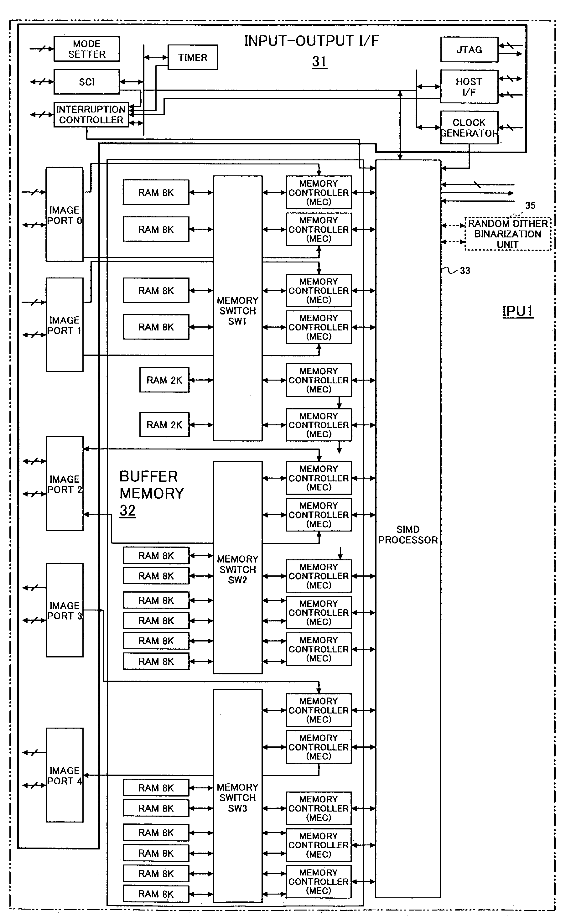
[0031]Still another specific object of the present, invention is to provide an image data processing device which can include an input-output interface enabling a high-speed processing using a same image processor both in a color image mode and a monochrome-image mode, and a multifunctional color image forming device having a high image-processing rate.
[0035]According to the present invention, the image processor is supplied with a plurality of the subject data sets arranged in integral bytes in a one-dimensional serial arrangement converted from the two-dimensional matrix data sets each composed of one-bit binary pixel information data items each corresponding to one pixel, wherein the processor elements of the image processor judges whether or not the respective subject data sets match the reference data; accordingly, judgements as to a plurality of two-dimensional matrix data sets can be obtained at one time. Additionally, the judgment is performed by a byte-data comparison of comparing each of the subject data sets having integral bytes with he reference data having the same integral bytes; therefore, the judgment can be performed at high speed.
[0037]According to the present invention, by using the dividing function of the memory controller in a monochrome image mode, for example, one series (e.g., one line) of monochrome image data can be divided into n series (e.g., two series of a string of image data items of odd-numbered pixels and a string of image data items of even-numbered pixels), and the image data items of the respective series can be supplied to the image processor simultaneously in parallel, and be processed by the image processor simultaneously in parallel. Therefore, the monochrome image data can be processed at high speed. Further, by using the synthesizing function of the memory controller, the processed image data items of the n series can be synthesized into one line of the processed image data items so as to be output. Therefore, the processed image data items can be transferred through a data transfer line of a monochrome image processing system. These functions can be used also for image data of one color for one line in a color image mode that the image data can be processed at high speed.

Problems solved by technology

Color image process and adjustment includes a variety of data conversions or data corrections, as mentioned above, which involves problems such as taking a lot of time for processing image data, and requiring a large memory for processing data.
For example, supposing that a variety of image processes are performed by a processor provided exclusively for image processes in an image processing device, such as a digital copying machine or a multifunctional machine, increases of processes and data typical of color devices decrease the processing rate.
Especially in a color image reading (by a color scanner) and a color image formation (by a color printer), a processing amount in a color γ conversion becomes a serious problem.
Accordingly, the color γ conversions using these LUTs consume a lot of time.
Thereby, two colors (two series) or more of image data strings can be processed simultaneously in parallel in the color-image mode so as to increase the processing rate several times. In this case, however, since two colors (two series) or more of image data need to be transferred simultaneously in the color-image mode, the above-mentioned image processor cannot be used simply by a conventional image processing system having only one data transfer line exclusively for monochrome image data.
Additionally, when the color processing machine using the above-mentioned image processor transfers and processes monochrome image data in the monochrome-image mode as performed in a conventional monochrome processing machine, the monochrome image data is processed series by series despite the image processor capable of processing two series or more of image data simultaneously; thus, the above-mentioned image processor cannot be fully utilized in the monochrome-image mode.
Thus, the signal processing device is not suitable for accelerating data conversion as above.
However, at boundaries between these three areas, properties of image data become discontinuous so as to cause image deterioration.
That is, a character image edge may become blurred, or when the image data has a high density, white spots may appear in a black part.
However, this pattern comparison is performed to each of the pixels composing the pixel matrix one by one; therefore, the matching for the entire pixel matrix takes a long time.
Therefore, the digital full-color copying machine involves data amounts and image processes several times as many as a monochrome copying, which largely increases a data processing time.
However, this decreases the image processing rate of the image processor.

Method used


Image

  • Image data processing device processing a plurality of series of data items simultaneously in parallel
  • Image data processing device processing a plurality of series of data items simultaneously in parallel
  • Image data processing device processing a plurality of series of data items simultaneously in parallel

Examples


embodiment 1

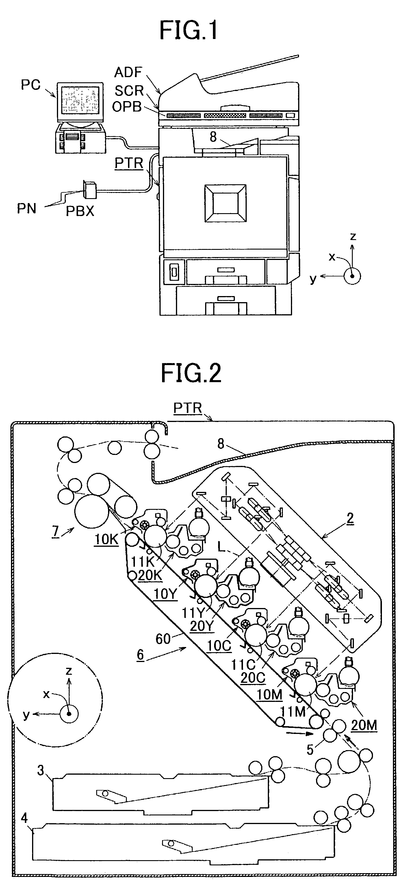
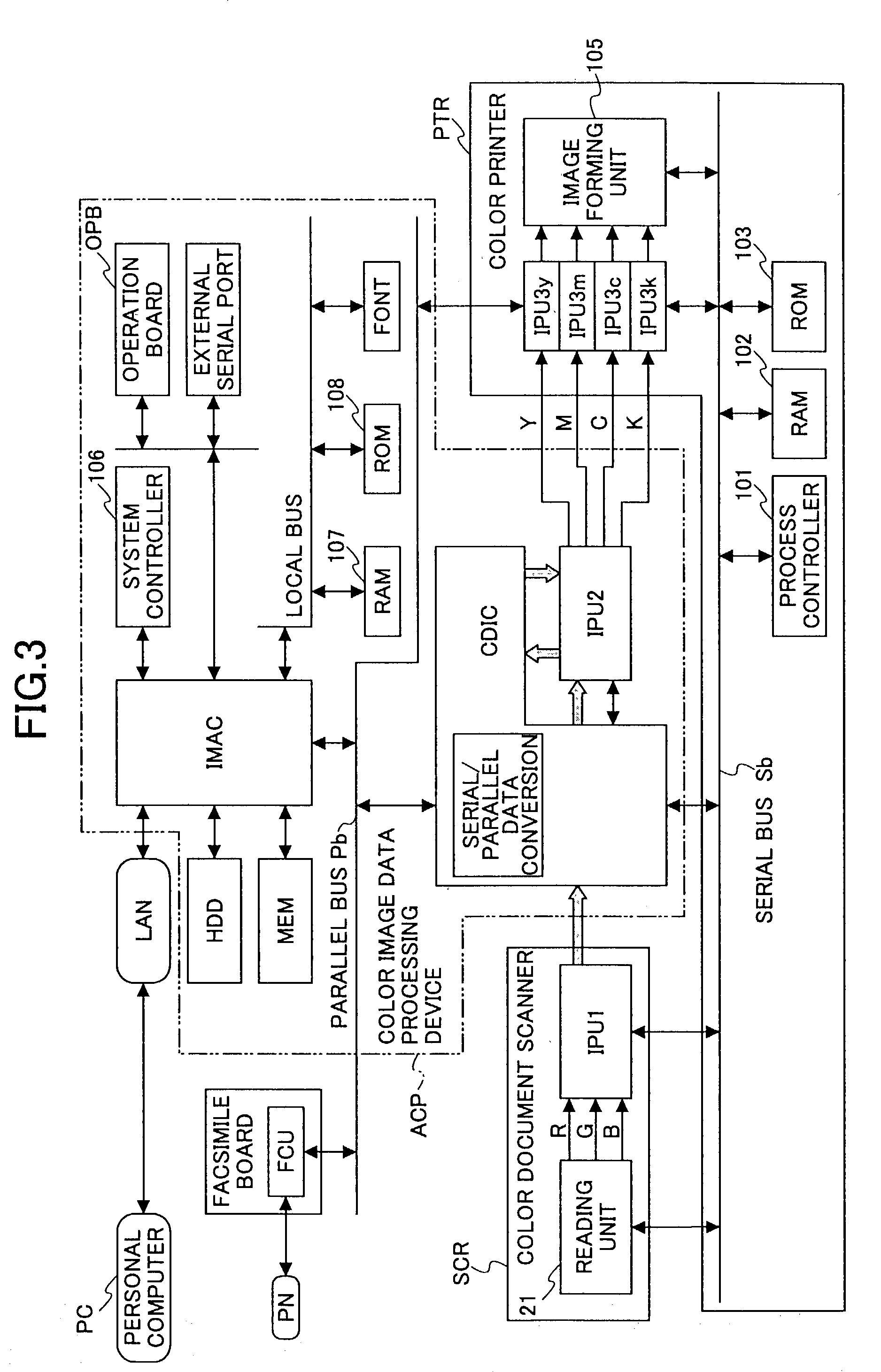
[0082]FIG. 1 is an illustration of a multifunctional full-color digital copying machine according to a first embodiment of the present invention. This full-color copying machine mainly comprises an automatic document feeder ADF, an operation board OPB, a color scanner (an image reader) SCR, and a color printer (an image former) PTR. A color image data processing device ACP (shown in FIG. 3) provided in the machine is connected to a LAN (Local Area Network) that is connected to a personal computer PC, and an exchanger PBX that is connected to a phone network PN (a facsimile communication network). The exchanger PBX is connected to a facsimile control unit FCU (shown in FIG. 3) of a facsimile board. A printed sheet is delivered from the printer PTR onto a delivery tray 8.

[0083]FIG. 2 shows a mechanism of the color printer PTR. The color printer PTR according to the present embodiment is a laser printer. This laser printer PTR comprises four toner-image forming units for forming images...

embodiment 2

[0189]Hardware according to a second embodiment is the same as in the foregoing first embodiment; however, the second embodiment has different data processes in an interpolative calculation of the γ conversion for generating LUTs.

[0190]FIG. 19 is a flowchart of the γ conversion for generating LUTs (a generation of LUTs for a scanner γ conversion in the IPU1, and a generation of LUTs for printer γ conversions in the IPU3y, the IPU3m, the IPU3c and the IPU3k) performed by the IPU1, the IPU3y, the IPU3m, the IPU3c and the IPU3k of the second embodiment.

[0191]First, the global bus processor (38) of the SIMD processor (33) according to the second embodiment initializes all of the processor elements PE0 to PEn, and sets n+1 (n=255) items D0 to Dn of gradation data representing 0-255 in the respective input registers of the n+1 processor elements PE0 to PEn (step aγp1).

[0192]Next, the global bus processor (38) determines the first section (i=1) as a section i to be calculated (step aγp2), ...

embodiment 3

[0201]Hardware according to a third embodiment is the same as in the foregoing first embodiment; however, in the third embodiment, an interpolative calculation program used in a generation of LUTs for γ conversions has a different configuration A description will be given of γ conversions (a generation of LUTs for a scanner γ conversion in the IPU1, and a generation of LUTs for printer γ conversions in the IPU3y, the IPU3m, the IPU3c and the IPU3k) performed by the IPU1, the IPU3y, the IPU3m, the IPU3c and the IPU3k of the third embodiment.

[0202]A reading-correction program for the IPU1 includes a storage address S00 of a scanner γ conversion program inserted at a location of the generation of γ conversion LUTs, as shown in FIG. 20. When the reading-correction program is transferred from the HDD to the program RAM 36 of the SIMD processor 33 of the IPU1, the scanner γ conversion program at the storage address S00 is replaced with the storage address so as to be transferred. In addit...


PUM


Abstract

In a data conversion device, a plurality of series of data to be converted is input from a buffer memory device to a data processor. The data processor processes a plurality of the series of the data to be converted, simultaneously in parallel, and outputs a plurality of the series of the data to be converted, simultaneously in parallel. A memory controller of the buffer memory device relates a plurality of the series of the data to be converted to respective conversion tables formed therein by the data processor so as to read converted data corresponding to the series of the data to be converted from the respective conversion tables simultaneously in parallel.

Description

BACKGROUND OF THE INVENTION[0001]1. Field of the Invention[0002]The present invention generally relates to a data conversion device, an image data processing device, a data conversion method, a pattern matching method, and an image data processing method, and more particularly, to an image processing device using the data conversion device, and an image processing device using the image data processing device.[0003]2. Description of the Related Art[0004]As a processing capacity and a processing rate of a computer has been improved, a data processing amount by a computer has been increased, more often involving data conversions or corrections. For example, there are a variety of image data processes, such as: reading corrections (a CCD inter-line correction, a main-scanning resist adjustment, a shading correction, a dot correction, a vertical stripe correction, a γ conversion, etc.) for compensating or correcting reading distortions of RGB image data read by a document scanner; an im...

Claims


Application Information

Patent Timeline
IPC IPC(8): G06K9/36G06F15/00G06F3/12H04N1/407
CPCH04N1/32561H04N1/32587H04N1/32603H04N1/407H04N1/32593H04N2201/0094
Inventor NOMIZU, YASUYUKI
Owner RICOH KK
Learn More