
Method for Graphically Generating Rounded-End Lines

Inactive Publication Date: 2007-09-27
THALES SA
View PDF15 Cites 19 Cited by
  • Summary
  • Abstract
  • Description
  • Claims
  • Application Information

AI Technical Summary

Benefits of technology

[0007] The object of the invention is to replace the rectangular elementary lines with lines having rounded ends so as to eliminate this problem.

Problems solved by technology

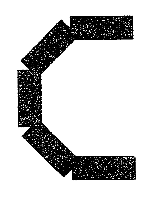
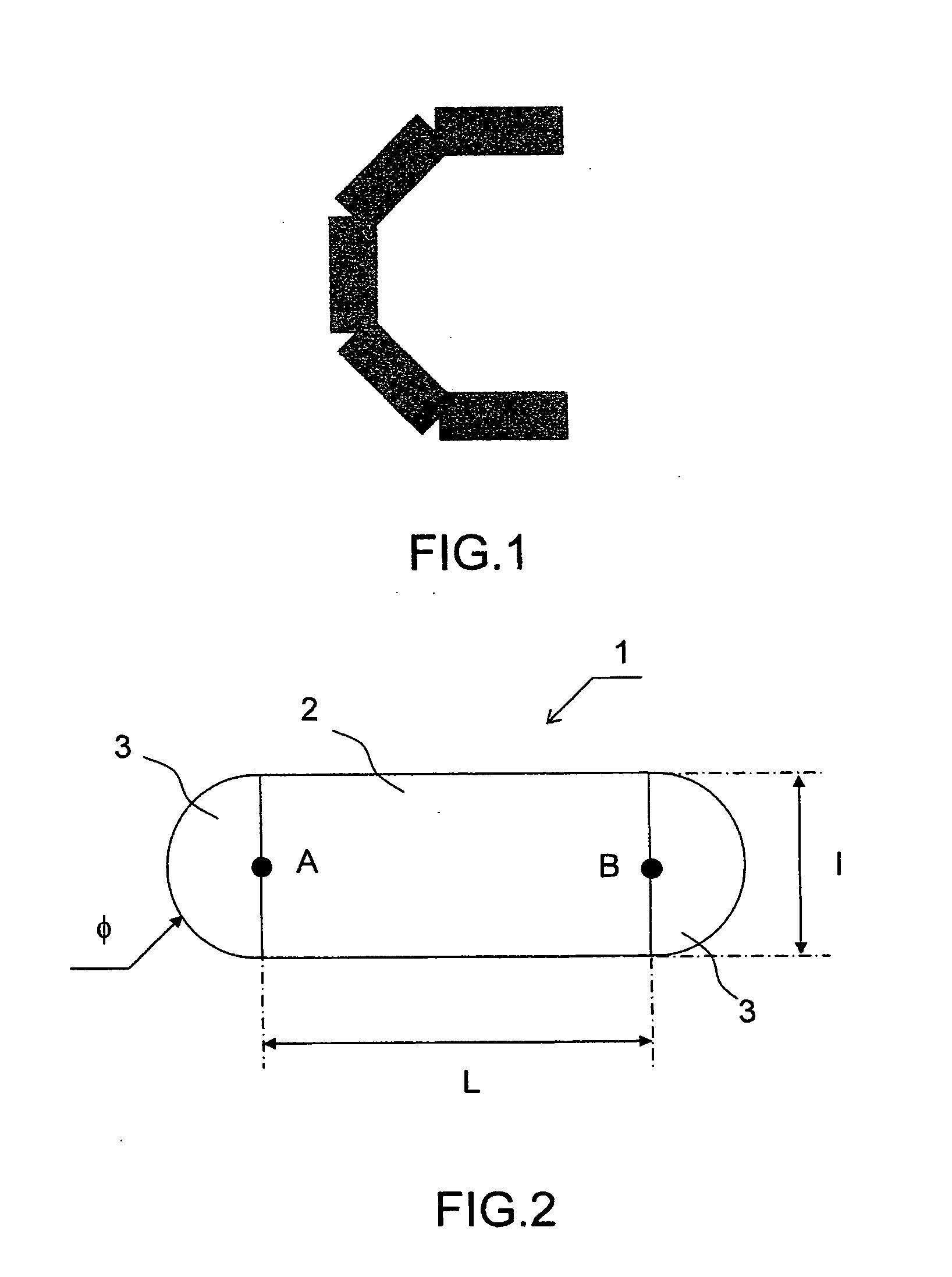
When a thick broken line is created on the basis of these elementary rectangles, discontinuities are obtained at the junction of two adjacent rectangles as indicated in FIG. 1 which represents the letter C. These discontinuities are visually rather unesthetic and can give rise to confusions between two neighboring symbols.

Method used


Image

  • Method for Graphically Generating Rounded-End Lines
  • Method for Graphically Generating Rounded-End Lines
  • Method for Graphically Generating Rounded-End Lines

Examples


Embodiment Construction

[0030]FIG. 2 represents a line 1 according to the invention. It comprises: [0031] a rectangular line body 2, the width l of the rectangle being equal to the thickness of the line and the length L of the rectangle to the length of the line, [0032] Two half-disks 3 centered on the sides of the rectangle of dimension equal to the thickness of the line, said half-disks having a diameter φ equal to this same thickness, the centers A and B of each circle delimiting the half-disks being merged with the centers of the sides of the rectangles corresponding.

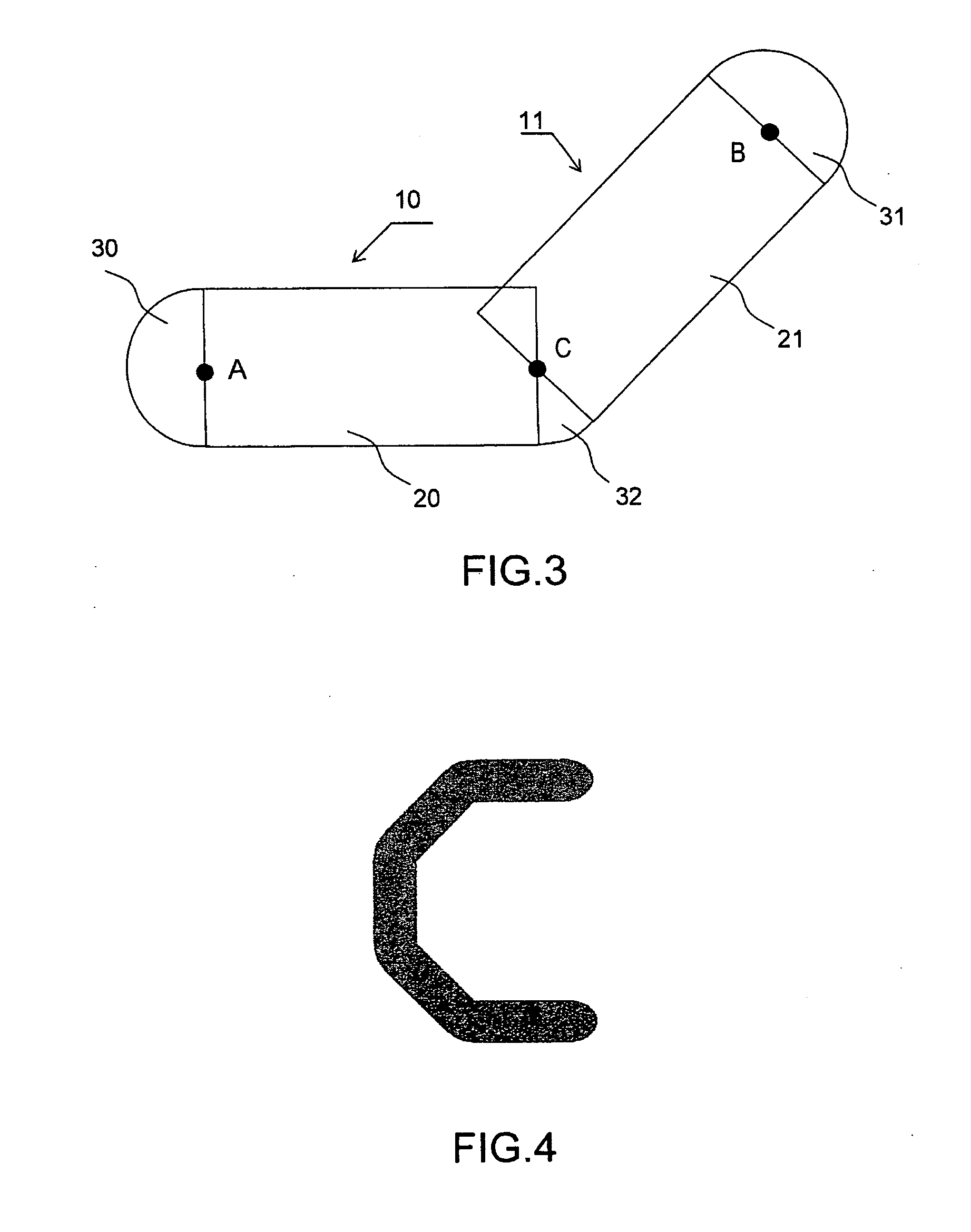
[0033]FIG. 3 represents the generation of a broken line consisting of two elementary straight lines 10 and 11 according to the invention. It comprises: [0034] a first line body 20 corresponding to the line 10; [0035] a second line body 21 corresponding to the line 11, the point of intersection C common to the sides of the first line body 20 and of the second line body 21 is situated at the center of the intersected sides of said bodies 20...


PUM


Abstract

The field of the invention is that of graphical libraries providing graphical functions used for drawing symbologic images. The object of the invention is to replace the rectangular elementary lines with lines having rounded ends so as to eliminate the problems of artifacts which appear when a thick line is represented by a simple rectangle. The invention describes the various steps of the graphical method of generating lines according to the invention in the case involving elementary lines or open or closed broken lines.

Description

CROSS-REFERENCE TO RELATED APPLICATIONS [0001] The present Application is based on International Application No. PCT / EP2005 / 051043, filed on Mar. 9, 2005, which in turn corresponds to France application Ser. No. 04 / 04147 filed on Apr. 20, 2004, and priority is hereby claimed under 35 USC §119 based on these applications. Each of these applications are hereby incorporated by reference in their entirety into the present application.BACKGROUND OF THE INVENTION [0002] 1. Field of the Invention [0003] The field of the invention is that of graphical libraries providing graphical functions used for drawing symbologic images. One of the fields of favored application is the generation of symbologic images for the piloting of aircraft. These images are in particular used for navigation, piloting and management of critical systems, such as engine checks. [0004] 2. Description of the Prior Art [0005] The graphical images are generated on matrix screens, such as, for example, liquid crystal disp...

Claims


Application Information

Patent Timeline
IPC IPC(8): G06T11/20G06T11/40
CPCG06T11/40G06T11/203
Inventor ARNEAU, DAVIDFILLIATRE, ERIC
Owner THALES SA
Learn More