Magnetic head with air bearing surface protection film
a protection film and magnetic head technology, applied in the field of magnetic head, can solve the problems of reducing the distance between the magnetic head and the magnetic disk to an utmost limit, lowering the adhesion property, and lowering the mechanical wear resistance, so as to improve the corrosive resistance, reduce the thickness of the air bearing surface protection film, and reduce the distance between the head and the disk
- Summary
- Abstract
- Description
- Claims
- Application Information
AI Technical Summary
Benefits of technology
Problems solved by technology
Method used
Image
Examples
example 1
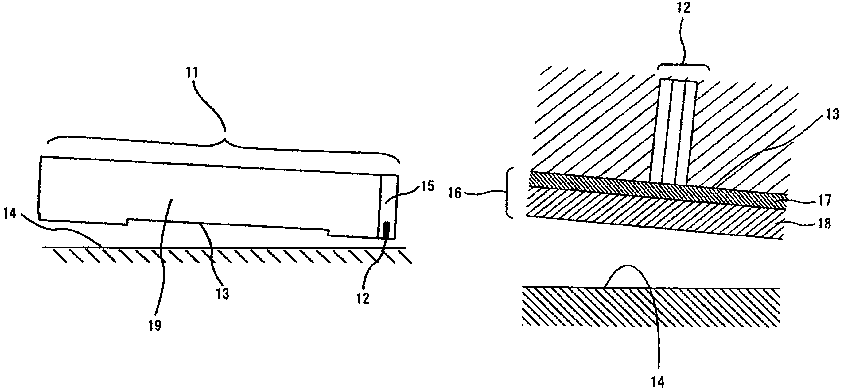
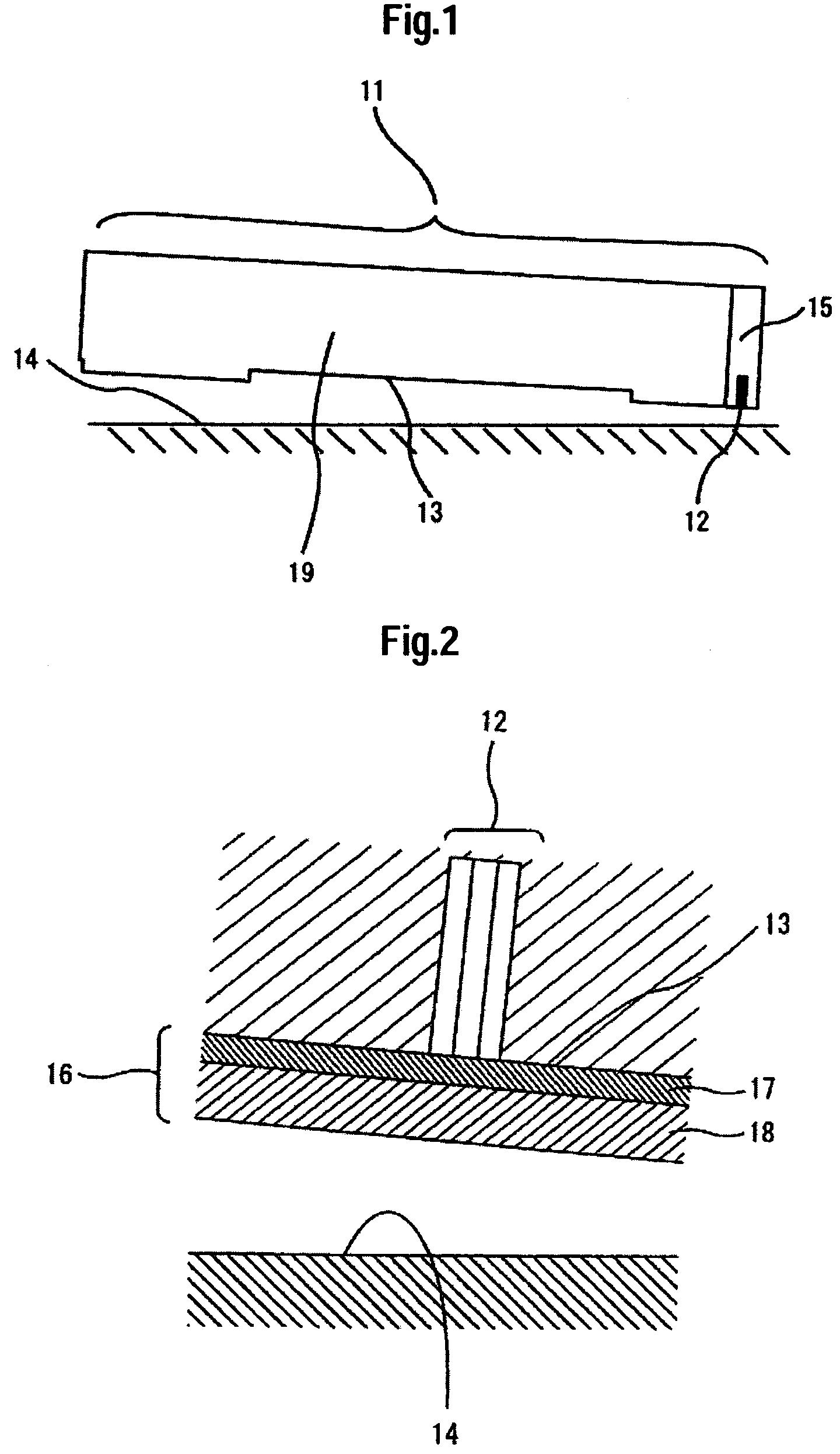
[0061]A process flow concerning the preparation of a protection film for a magnetic head air bearing surface according to an embodiment of the present invention is to be described. At first, the magnetic head 11 is transported into a vacuum chamber, which is then evacuated. In this case, the magnetic head may be in a slider shape or in a bar shape. Subsequently, the air bearing surface is etched by using plasma or ion beams with Ar or other rare gas. The etching is used for removing machined surface layer, oxide layer, etc. during fabrication of the magnetic head air bearing surface. While it is not always a necessary step in the invention, it is preferably practiced.
[0062]Successively, the lowermost air bearing surface protection film 17 is formed. In the present embodiment, the lowermost air bearing surface protection film 17 is formed of a silicon nitride film. In Example 1, the silicon nitride film is formed by reactive sputtering. In Example 1, a sputtering gas is introduced at...
example 2
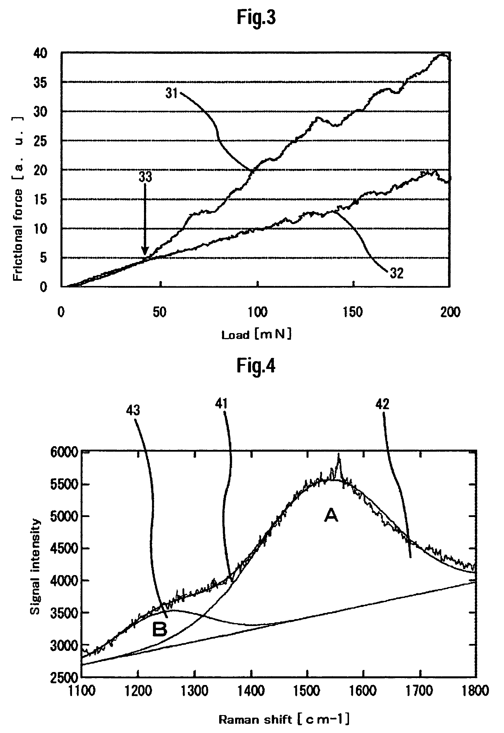
[0074]The uppermost air bearing surface protection film 18 according to the present embodiment is a film comprising tetrahedral amorphous carbon and nitrogen. As has been described above, the corrosive resistance is not excellent in a case where the uppermost air bearing surface protection film 18 comprises amorphous carbon formed by the sputtering deposition method or hydrogen-containing amorphous carbon formed by the CVD method. No sufficient reliability can therefore be attained on the magnetic head when the extremely thin air bearing surface protection film is formed at a total film thickness of 3.0 nm or less. Since the film quality of the tetrahedral amorphous carbon film shows a characteristic result when a quantitative element analysis method such as Raman spectrometry and TOF-SIMS or RBS (Rutherford Backscattering Spectrometry) is used, the tetrahedral amorphous carbon film can be distinguished from other amorphous carbon films. The features of the tetrahedral amorphous car...
example 3
[0092]In FIG. 11, abscissa expresses the film thickness and the ordinate expresses the number of pinholes for a silicon film and a silicon nitride film. The silicon film and the silicon nitride film were prepared by using the sputtering deposition method and the reactive sputtering deposition method, respectively. According to FIG. 11, the thin silicon nitride film exhibits smaller number of pinholes than that of the thin silicon film at an identical film thickness. That is, the thin silicon nitride film is excellent in the corrosive resistance and the electrical insulative property and has greater number of bondings attributable to adhesion with the uppermost air bearing surface protection film 18. In the reactive sputtering, a film was formed while the nitrogen flow ratio in the sputtering gas is changed from 10% to 50% as shown in FIG. 11.
[0093]In view of FIG. 11, when a thin silicon nitride film is prepared under certain conditions, the number of pinholes in the film with a thic...
PUM
| Property | Measurement | Unit |
|---|---|---|
| thickness | aaaaa | aaaaa |
| thickness | aaaaa | aaaaa |
| thickness | aaaaa | aaaaa |
Abstract
Description
Claims
Application Information
 - R&D
- Intellectual Property
- Life Sciences
- Materials
- Tech Scout
- Unparalleled Data Quality
- Higher Quality Content
- 60% Fewer Hallucinations
Browse by: Latest US Patents, China's latest patents, Technical Efficacy Thesaurus, Application Domain, Technology Topic, Popular Technical Reports.
© 2025 PatSnap. All rights reserved.Legal|Privacy policy|Modern Slavery Act Transparency Statement|Sitemap|About US| Contact US: help@patsnap.com


