
Flexible die and method for its manufacture

a technology of flexible dies and dies, applied in the field of flexible dies, can solve the problems of deteriorating blade durability and affecting precision machining, and achieve the effects of enhancing punching machining precision, small base width, and less pressur

Inactive Publication Date: 2007-10-23
TSUKATANI HAMONO MFG CO LTD
View PDF30 Cites 2 Cited by
  • Summary
  • Abstract
  • Description
  • Claims
  • Application Information

AI Technical Summary

Benefits of technology

"The present invention relates to a flexible die with a push-cutting blade and a method for manufacturing it. The push-cutting blade is formed by etching a flexible base and a projection that protrudes from it. The blade has a smaller base width than conventional flexible dies, which enhances machining precision and reduces interference with the material being punched. The blade is sharpened at the tip, which results in a smaller contact area and less pressure during the punching operation. The manufacturing method involves laminating a photoresist layer on a metal plate, etching the plate to a predetermined depth, and shaping the vertical projection by either cutting a lateral surface of the projection or sharpening its tip. The wire EDM process used in the manufacturing method imposes less mechanical force on the workpiece, allowing for precise inner profiling and inward taper of the blade."

Problems solved by technology

However, this configuration is detrimental to precision machining.
In addition, the triangular configuration may deteriorate the blade durability, because such push-cutting blade is subjected to a heavy pressure during the punching operation.

Method used


Image

  • Flexible die and method for its manufacture
  • Flexible die and method for its manufacture
  • Flexible die and method for its manufacture

Examples


Embodiment Construction

[0039]Embodiments of the present invention are hereinafter described with reference to the drawings.

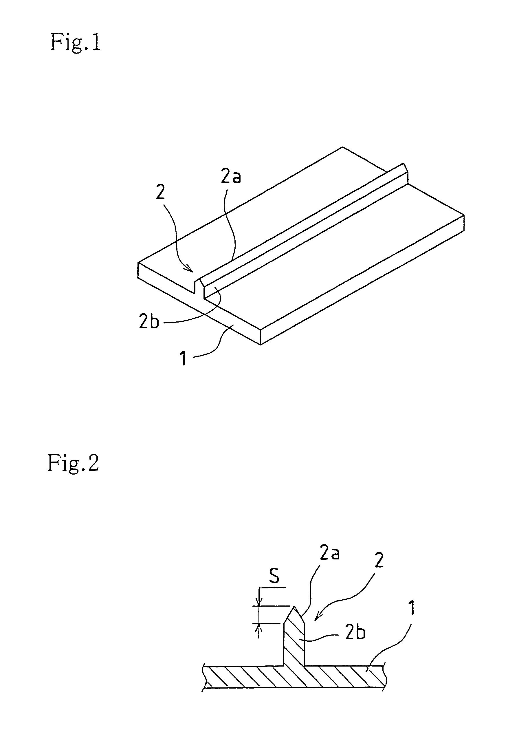
[0040]FIG. 1 shows, in perspective, the essential structure of a flexible die according to an embodiment of the present invention. FIG. 2 is a vertical section of this embodiment.

[0041]A flexible die of this embodiment is composed of a flexible base 1 and a push-cutting blade 2 formed on one surface thereof. Regarding the push-cutting blade 2, a vertical projection 2b protrudes vertically from the flexible base 1, with the tip being sharpened to give a double cutting edge 2a.

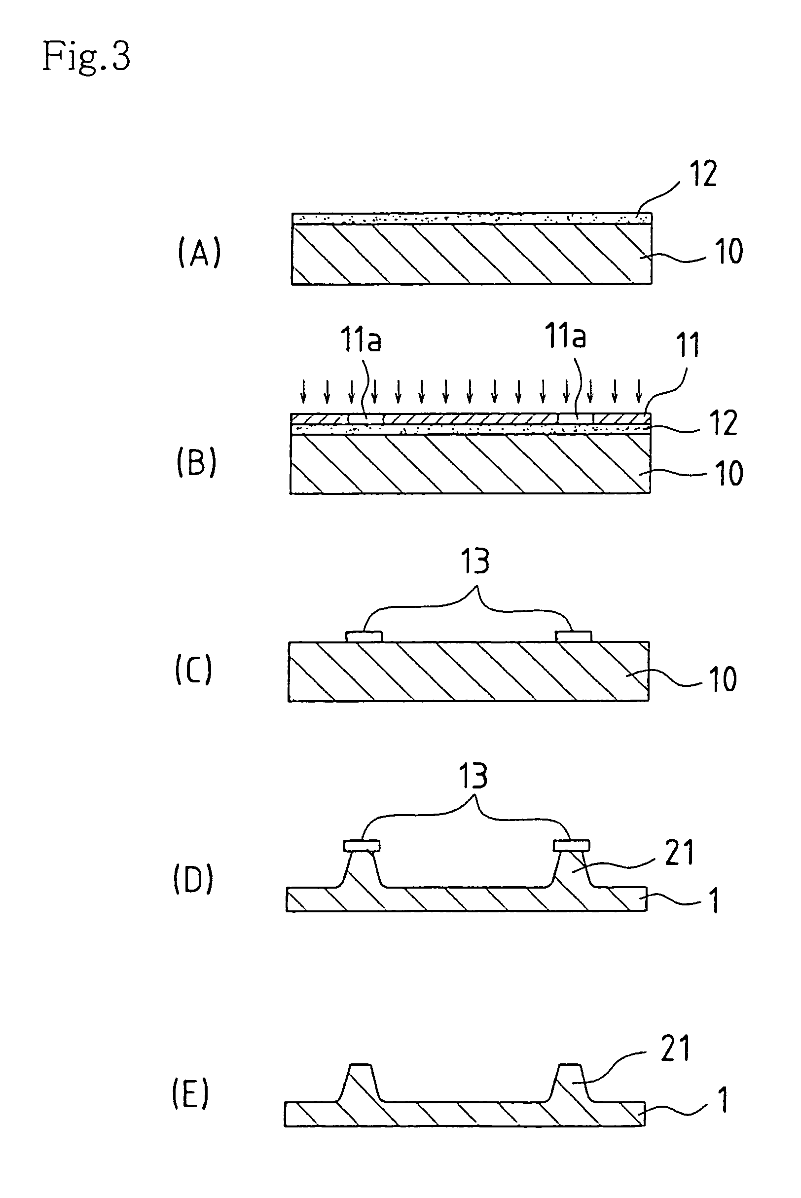
[0042]The flexible die shown in FIG. 1 is manufactured in the manner as described below and illustrated in FIG. 3, FIG. 4, FIG. 14 and FIG. 15.

[0043](1) Prepare a photomask (film) 11, according to an exposure pattern 11a shown in FIG. 14 (The pattern corresponds to the profile line 103 in FIG. 16.).

[0044](2) Apply a photoresist uniformly on the surface of a metal plate 10 which is a 0.50-mm-thick ferromagnetic st...


PUM

PropertyMeasurementUnit
widthaaaaaaaaaa
widthaaaaaaaaaa
included angleaaaaaaaaaa

Abstract

To obtain a push-cutting blade 2, a flexible base 1 and a projection (trapezoid-section projection 21) protruding from this base are formed by etching. Then, a lateral surface or surfaces of the projection 21 is cut into a vertical projection 2b. Lastly, the tip of the vertical projection 2b is sharpened to give a double (or single) cutting edge 2a.

Description

CROSS REFERENCE TO RELATED APPLICATIONS[0001]The present application is a Divisional Application of the patent application Ser. No. 10 / 451,527, filed Jun. 24, 2003, now abandoned, which is based on Priority Document JP-2000-400012 filed on Dec. 28, 2000.TECHNICAL FIELD[0002]The present invention relates to a flexible die (sheet-like blade plate) which is used to cut (push-cut) a piece of thin paper, plastic sheet or the like along a given profile line, and a method for its manufacture.BACKGROUND ART[0003]In the field of printing machines, a flexographic printing machine has been put to practical use. This type of printing machine is composed of a magnet roll whose surface is laminated with a magnet chip. To perform printing, a flexible printing plate containing a ferromagnetic material (e.g. iron, ferrite, cobalt, nickel) is attached (sucked) on the magnetic roll. An advantage of the flexographic printing machine resides in its capacity to change the print image in a simple manner, ...

Claims


Application Information

Patent Timeline
Patent Type & Authority Patents(United States)
IPC IPC(8): B21K5/20B23P15/40B26F1/44
CPCB23P15/406B26F1/44B26F1/384Y10T29/53996B26F2001/4472Y10T29/53161B26F2001/4436Y10T83/9466
Inventor MISAKI, KAORU
Owner TSUKATANI HAMONO MFG CO LTD
Learn More