
Dual stage centrifugal liquid-solids separator

Inactive Publication Date: 2006-04-11
GRISWOLD CONTROLS LLC
View PDF12 Cites 45 Cited by
  • Summary
  • Abstract
  • Description
  • Claims
  • Application Information

AI Technical Summary

Benefits of technology

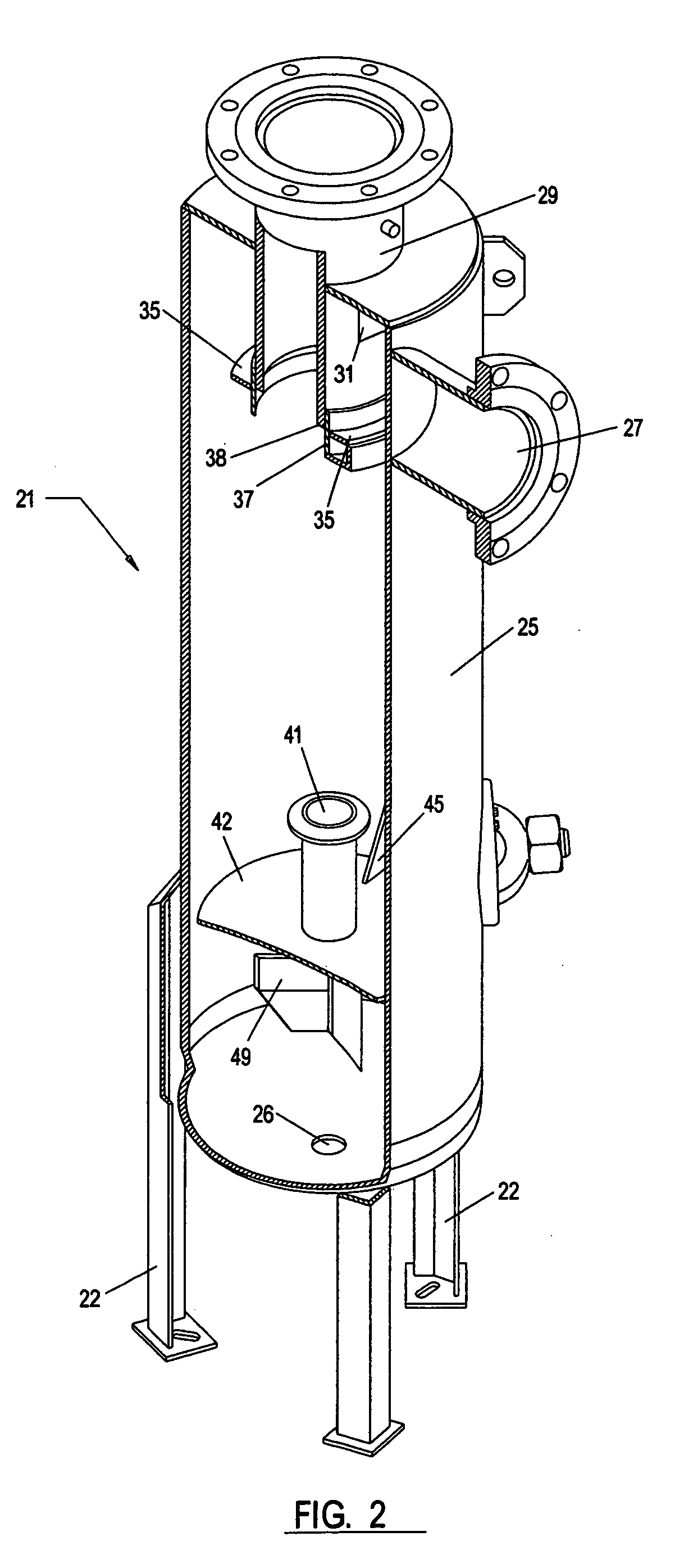
[0011]Meanwhile, the solids-laden fluid stream continues its downward spiral away from the center of the formed vortex. As the stream spirals downward in a decelerating motion, a much cleaner vortex is created at the center of the vessel. A reversing or upper spin plate is provided in the axial center of the chamber, reversing the cleaner flow at the center of the vortex, causing it to travel back upward. The higher the location of this upper spin plate, the less distance the fluid must travel and the less pressure that is lost. This is where the first separation takes place.
[0022]It is a further important object of the present invention to provide a vortex-based separator having a set of baffles in the lower collection chamber to prevent the solids from further spinning and to facilitate quiescent settling of the solids.

Problems solved by technology

When significant quantities of solids are present, it is impractical to use mesh filters since they will quickly clog and be rendered useless.
Unfortunately, the centrally located rotors in such designs take up considerable space which blocks much of the internal centrifugal flow.
However, as demonstrated by the many additional features found in later inventions, complete separation in a vortex-based centrifugal system has yet to be fully achieved.

Method used


Image

  • Dual stage centrifugal liquid-solids separator
  • Dual stage centrifugal liquid-solids separator
  • Dual stage centrifugal liquid-solids separator

Examples


Embodiment Construction

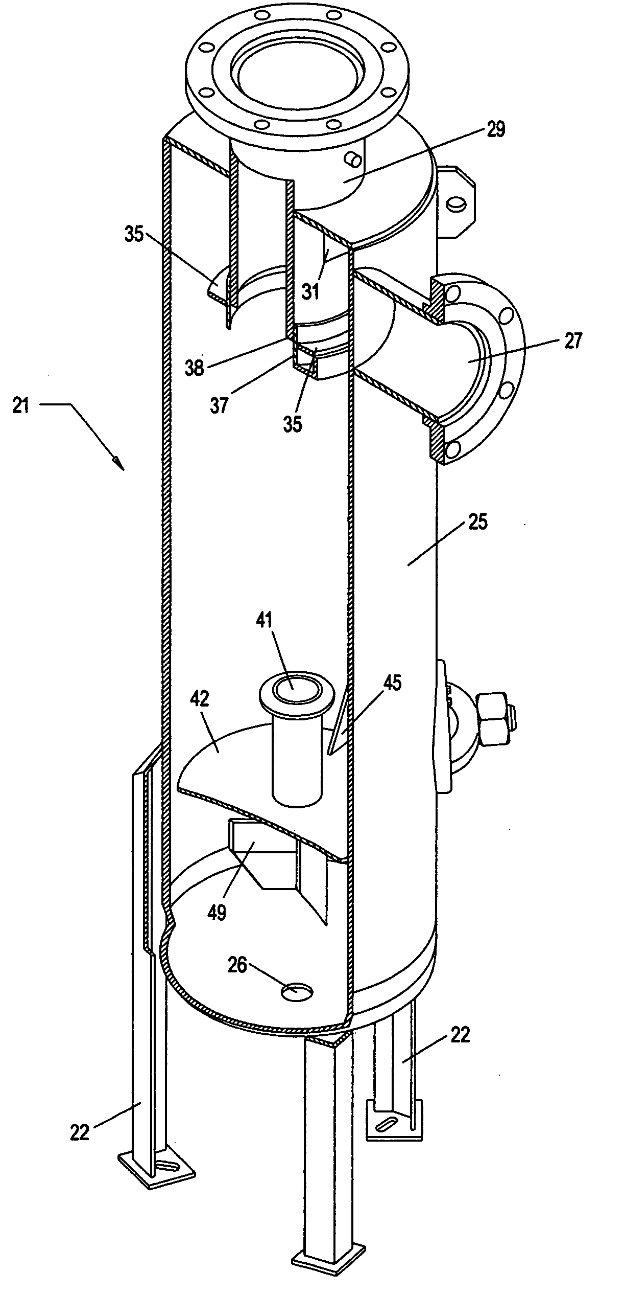
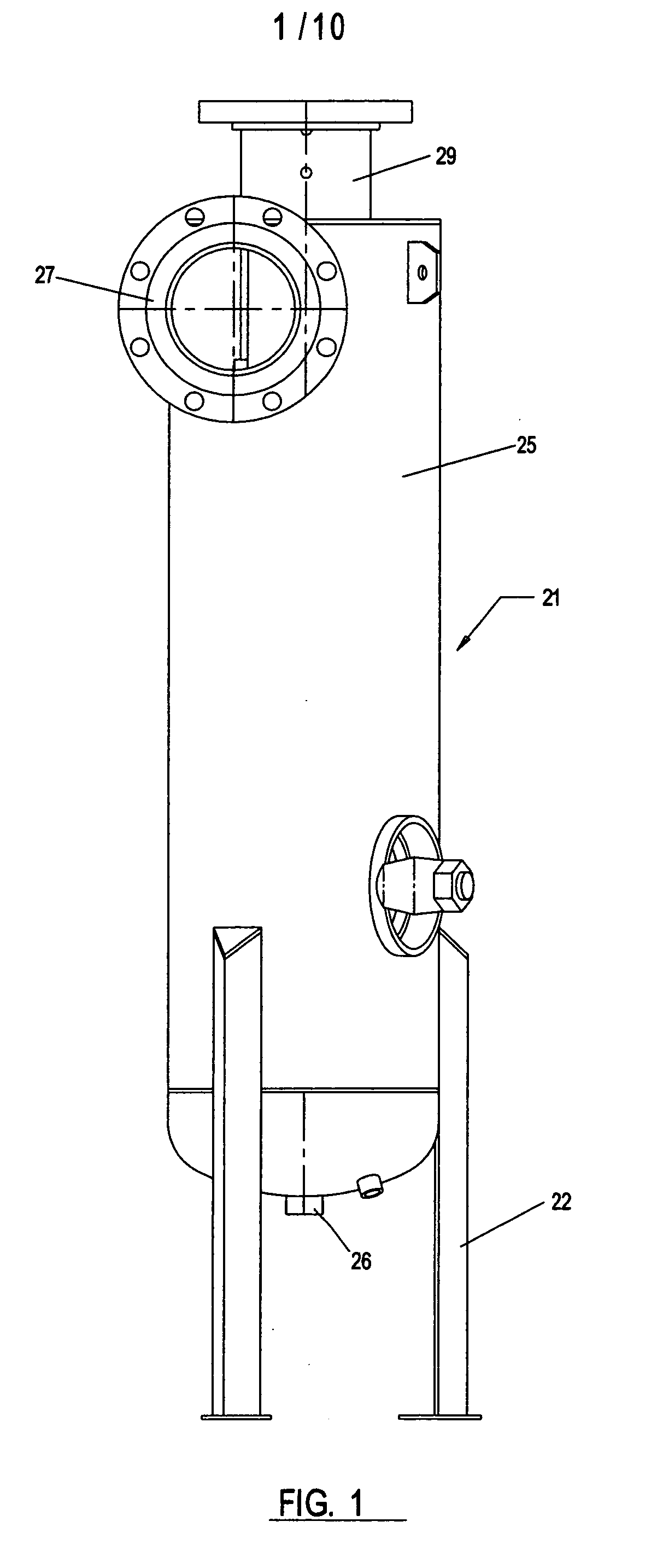
[0035]Referring to the drawings wherein like reference characters designate like or corresponding parts throughout the several views, and referring particularly to FIG. 2, it is seen that the invention includes a large vessel 21 supported by a set of exterior legs 22, the vessel having a cylindrical wall 25 defining an internal chamber 24. A lateral inlet pipe 27 is provided near the top of chamber 24 for receiving an incoming fluid stream containing liquid, solids and gasses (“fluid stream”). An adjustable slot or valve 28 is provided along inlet pipe 27 to vary the flow of the incoming pressure stream. Inlet pipe 27 is attached to vessel 21 in such a way that the fluid flow is introduced into chamber 24 at an angle that is generally tangential to cylindrical wall 25, as best illustrated in FIG. 4. This tangential introduction of fluid results in a rotational flow inside chamber 24. A central, axially aligned exit pipe 29 is provided at the top of vessel 21 leading from internal ch...


PUM

PropertyMeasurementUnit
Flow rateaaaaaaaaaa
Shapeaaaaaaaaaa
Velocityaaaaaaaaaa

Abstract

Disclosed is a vortex-based centrifugal separator for removing solids from a liquid / solids fluid stream in two stages. A fluid stream under pressure is introduced at the top of the cylindrical separator at a tangential angle forming helical downward flow. The first stage uses a centrally-located spin plate for reversing the cleaner interior flow of the vortex back upward, while the heavier solids settle at the bottom of the chamber for periodic removal. In the second stage, a plurality of louvered slots in an upper discharge pipe remove finer solids from the exiting upward fluid flow prior to discharge.

Description

BACKGROUND OF THE INVENTION[0001]1. Field of the Invention[0002]The present invention relates to solid-liquid separators, and more particularly to a new and improved device for centrifugally separating solids from liquids in a liquid / solid mixture in two distinct separation stages that occur during a single pass of the mixture through the device.[0003]2. Description of the Prior Art[0004]It is often desirable to separate solid particles from liquid / solid mixtures or slurries to clarify or purify the remaining liquid. When significant quantities of solids are present, it is impractical to use mesh filters since they will quickly clog and be rendered useless. As a result, centrifugal liquid-solid separators have been developed in the prior art. These devices utilize centrifugal force and gravity to achieve varying degrees of separation of solids from solid / liquid mixtures. The separated solids generally settle to the bottom of the centrifugal chamber from which they are periodically r...

Claims


Application Information

Patent Timeline
IPC IPC(8): B01D21/26B01D17/038B01D19/00B01D21/00
CPCB01D19/0057B01D21/0012B04C5/13B04C5/103B01D21/26B01D21/2494B01D21/245B01D21/2411B01D21/0024B01D21/0036B01D21/02B01D21/0039B01D21/0042
Inventor MOYA, EMMANUEL G.
Owner GRISWOLD CONTROLS LLC
Learn More