Optical amplifier having polarization mode dispersion compensation function
a technology of optical amplifier and dispersion compensation, which is applied in the field of optical amplifier, can solve the problems of not yet solving the space-saving of optical amplifier and optical device, no technical approach to realize and no common or shared technology for achieving the miniaturization of optical amplifier
- Summary
- Abstract
- Description
- Claims
- Application Information
AI Technical Summary
Benefits of technology
Problems solved by technology
Method used
Image
Examples
first embodiment
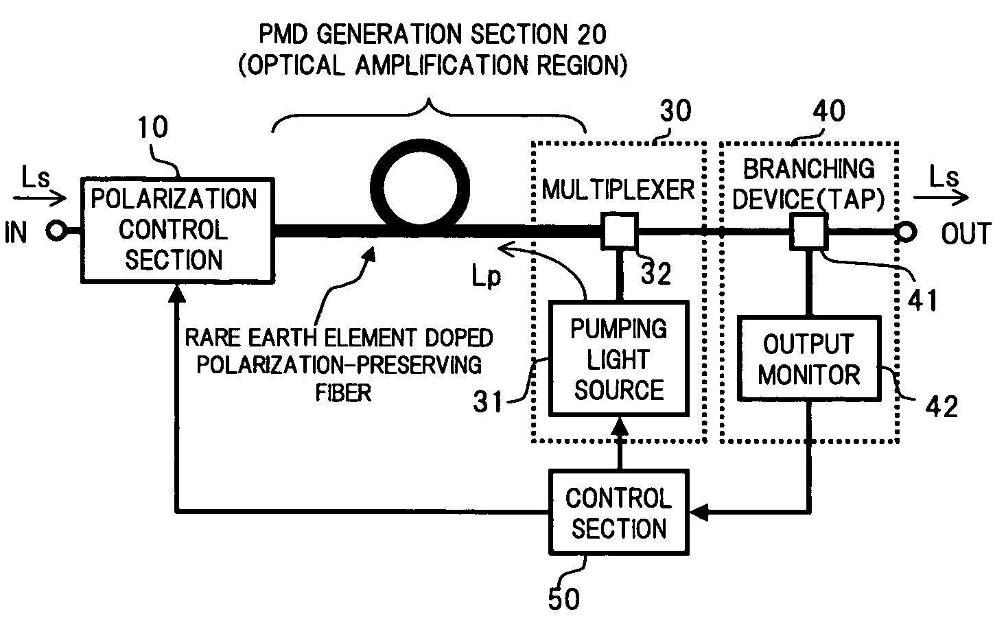
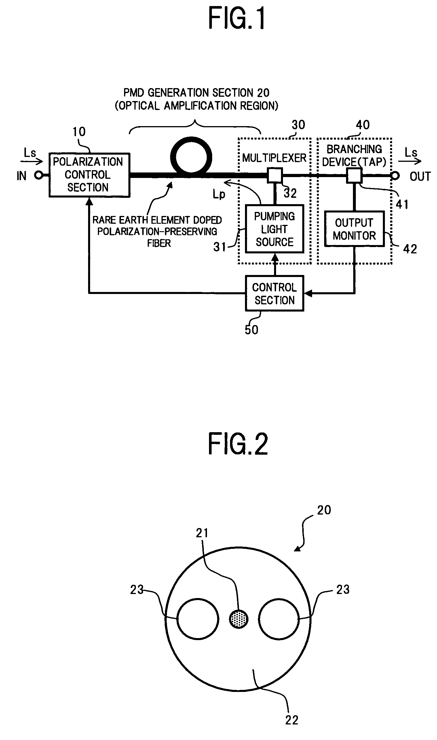
[0044]FIG. 1 is a functional block diagram showing the configuration of an optical amplifier according to the present invention.
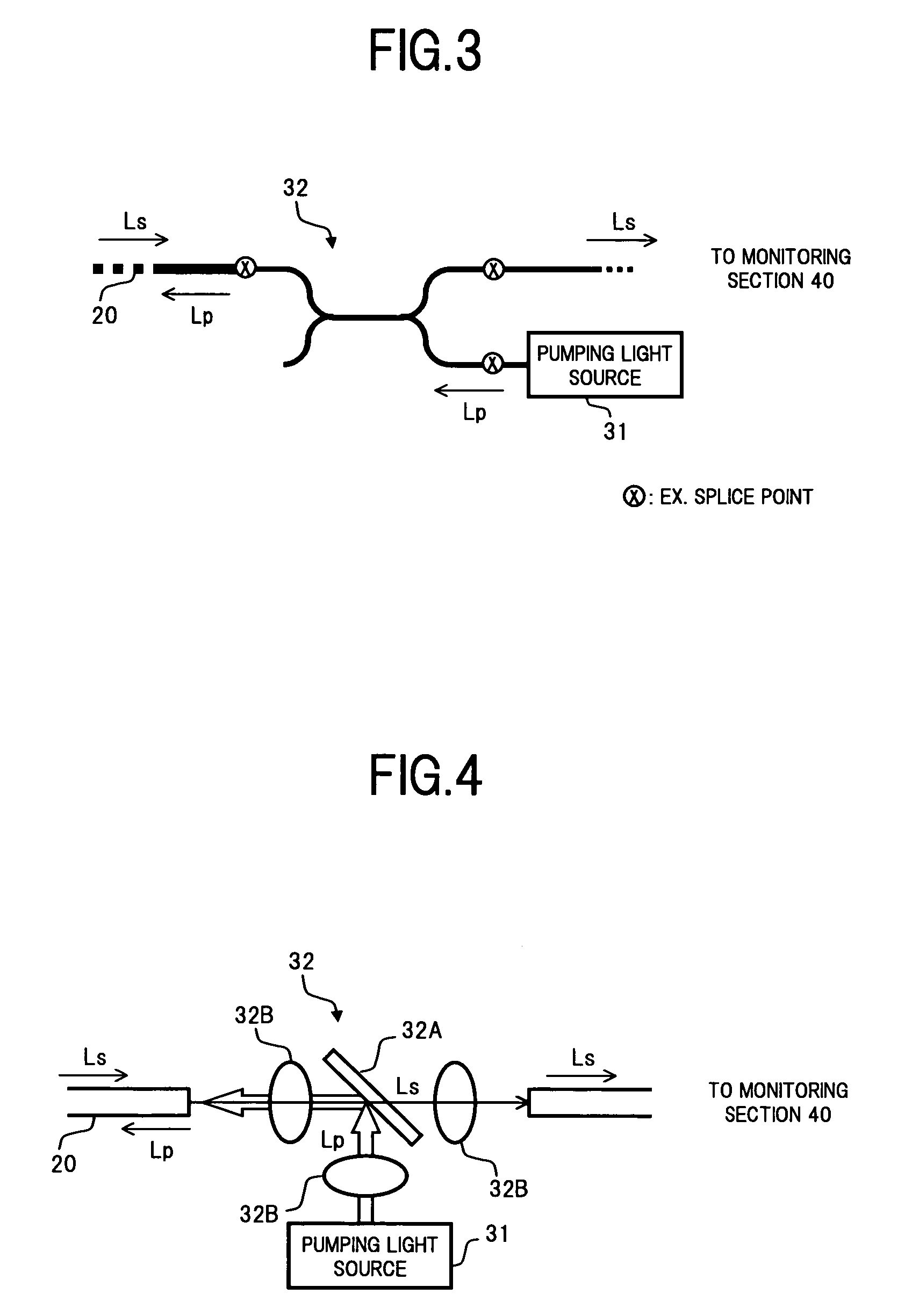
[0045]In FIG. 1, the optical amplifier in this embodiment comprises, for example: a polarization control section 10 that controls a polarization state of signal light Ls given to an input terminal IN; a PMD generation section 20 that receives the signal light Ls output from the polarization control section 10 at an optical transmission medium thereof having birefringence and doped with at least a rare earth element (ex. Er), and gives a required differential group delay (DGD) between orthogonal polarization mode components of the signal light Ls, to amplify the signal light Ls while performing PMD compensation; a pumping light supply section 30 that supplies pumping light to the optical transmission medium in the PMD generation section 20 to pump the rare earth element; a monitoring section 40 that monitors the power and PMD generation state of the signal l...
second embodiment
[0066]the optical amplifier according to the present invention will be described below.
[0067]FIG. 8 is a functional block diagram showing the configuration of the optical amplifier of the second embodiment.
[0068]In FIG. 8, a difference of the configuration of the optical amplifier in the second embodiment from that of the first embodiment is that a polarization control section 10′ and a PMD generation section 20′ constructed by using birefringence of an optical waveguide formed on a crystalline substrate formed of, for example, lithium niobate (LiNbO3:LN) and the like are provided, instead of the polarization control section 10 and the PMD generation section 20. Other than these sections, the respective configurations of the pumping light supply section 30, the monitoring section 40 and the control section 50 are the same as those in the first embodiment, and hence description thereof is omitted here.
[0069]As the configuration of the LN waveguide-type polarization control section 10...
third embodiment
[0081]the optical amplifier according to the present invention will be described below.
[0082]In the integrated configuration as described in the first and the second embodiments in which the PMD compensation and optical amplification are performed at the same time, in the respective configurations of the forward pumping type as shown in FIG. 6, and the bi-directional pumping type as shown in FIG. 7, there is a possibility that leaked light of the pumping light Lp being propagated in the same direction as the signal light Ls is input to the monitoring section 40, to decrease the monitoring accuracy of the PMD in the output monitor 42. In the third embodiment, an improvement example will be described, for preventing a decrease in the monitoring accuracy due to the influence of the leaked light of the pumping light Lp (residual pumping light).
[0083]FIG. 13 is a block diagram showing the configuration of the monitoring section used in the optical amplifier of the third embodiment.
[0084]...
PUM
 Abstract
Description
Claims
Application Information
 - R&D
- Intellectual Property
- Life Sciences
- Materials
- Tech Scout
- Unparalleled Data Quality
- Higher Quality Content
- 60% Fewer Hallucinations
Browse by: Latest US Patents, China's latest patents, Technical Efficacy Thesaurus, Application Domain, Technology Topic, Popular Technical Reports.
© 2025 PatSnap. All rights reserved.Legal|Privacy policy|Modern Slavery Act Transparency Statement|Sitemap|About US| Contact US: help@patsnap.com


