System and method for converting system management data to be viewed and updated before or during runtime of an operating system

Inactive Publication Date: 2007-07-10
SIEMENS AG
View PDF7 Cites 8 Cited by
  • Summary
  • Abstract
  • Description
  • Claims
  • Application Information

AI Technical Summary

Benefits of technology

[0007]It is an object of an embodiment of the invention to provide a process for the catalytic reduction of nitrogen oxides in the exhaust gas from a combustion system, by which nitrogen oxides which are present in the exhaust gas are broken down more effectively. Preferably, this is done using the selective catalytic reduction process, at low temperatures compared to a known similar process. A further object of an embodiment of the invention may be to provide an exhaust-cleaning system for the catalytic reduction of nitrogen oxides in the exhaust gas from a combustion system which allows the selective catalytic reduction process to be used at lower temperatures than a similar known device.
[0008]An object may be achieved, according to an embodiment of the invention, by an exhaust-gas temperature being measured and compared with a set temperature, and / or in the case of an exhaust-gas temperature that is lower than the set temperature, by the reagent being added to the exhaust gas before it flows through the oxidation catalytic converter, and / or in the case of an exhaust-gas temperature which is higher than the set temperature, by the reagent being added to the exhaust gas after it has flowed through the oxidation catalytic converter but before it flows through the reduction catalytic converter. An embodiment of the invention is based on the consideration that the rate at which nitrogen dioxide NO2 is formed from nitrogen monoxide NO at the oxidation catalytic converter connected upstream of the reduction catalytic converter decreases as temperatures fall below approximately 250° C., so that the lower the temperature, the lower the deNOxing rates which are achieved, even with a combination of oxidation catalytic converter and reduction catalytic converter in this lower temperature range.
[0013]In an exhaust-cleaning system with a combination of oxidation catalytic converter and reducing catalytic converter, introducing the reagent in front or upstream of the oxidation catalytic converter allows the residual activity of the oxidation catalytic converter in a temperature range below approximately 250° C. to be utilized to selectively break down nitrogen oxides into molecular nitrogen, so that the nitrogen oxides can be broken down more effectively in this temperature range than with a similar exhaust-cleaning system from the prior art.
[0015]In a particularly advantageous configuration of the invention, the set temperature is selected from a temperature range between 190° C. and 210° C. This is particularly advantageous when the process is used for a diesel engine. This is because it has emerged that at an exhaust-gas temperature which is below a set temperature selected from this range, at the space velocities which customarily prevail downstream of a diesel engine, the selectivity of standard precious-metal oxidation catalytic converters for the conversion of nitrogen oxides into molecular nitrogen increases.
[0017]It is preferable for an aqueous urea solution or aqueous ammonia to be injected as reagent into the exhaust gas via an injection nozzle. A liquid reagent allows a simpler metering technique than a solid reagent. Moreover, a liquid reagent is easier to handle than a gaseous reagent.
[0018]However, the process can, of course, also be carried out using a solid reagent, such as urea, or other substances which release ammonia. It is also conceivable to introduce gaseous ammonia or ammonia which has been released from ammonium carbamate. Compared to other reducing agents, such as for example hydrocarbons, ammonia has proven to be most effective for the use of the selective catalytic reduction process.

Problems solved by technology

However, a drawback is that the rate at which nitrogen dioxide NO2 is formed from nitrogen monoxide NO at the oxidation catalytic converter decreases considerably at temperatures below 200° C., so that at temperatures below 200° C. only insufficient deNOxing can be achieved even with a combination of oxidation catalytic converter and reduction catalytic converter.

Method used


Image

  • System and method for converting system management data to be viewed and updated before or during runtime of an operating system
  • System and method for converting system management data to be viewed and updated before or during runtime of an operating system

Examples


Embodiment Construction

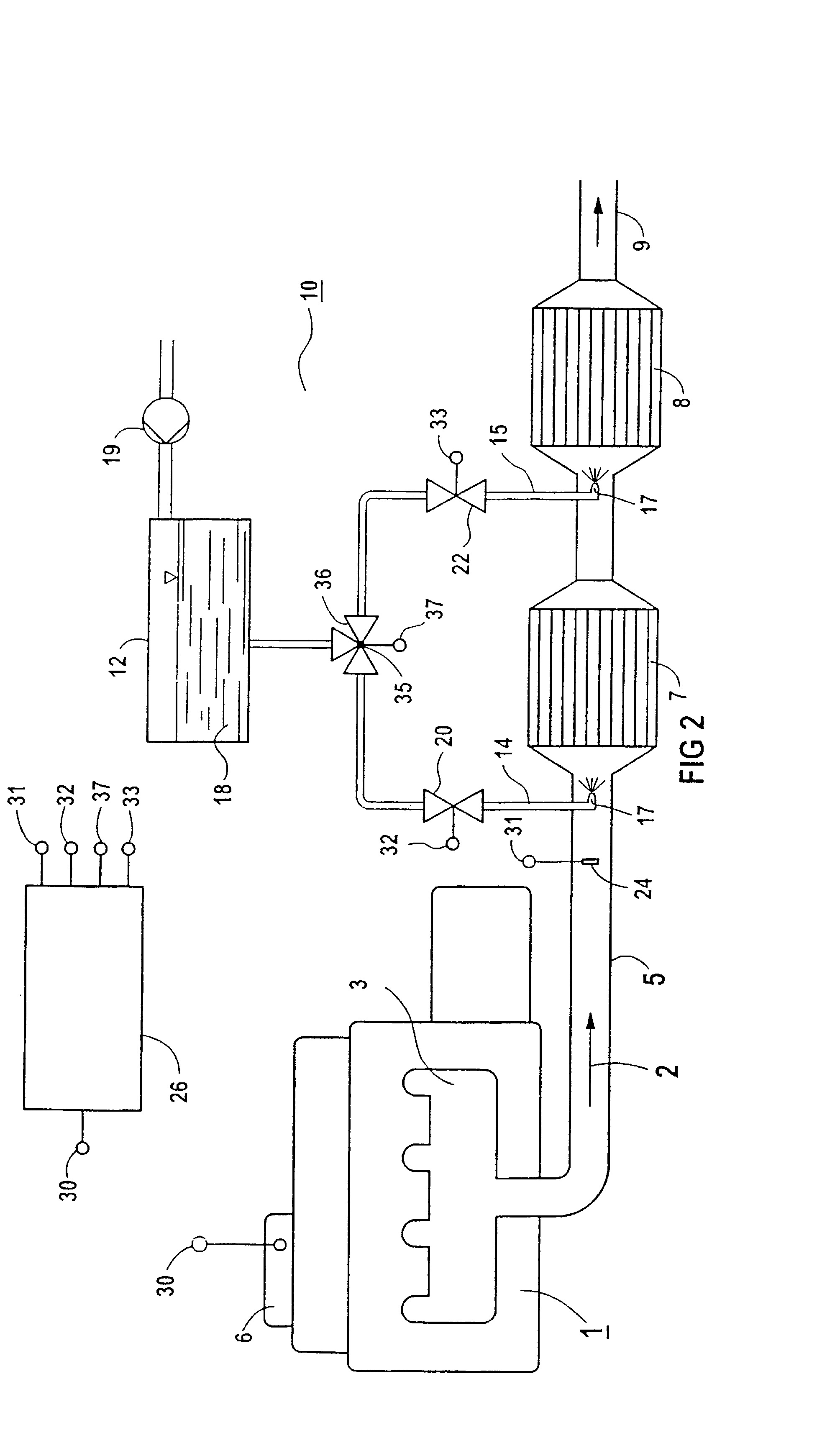
[0027]FIG. 1 diagrammatically depicts an exhaust-cleaning system for a combustion system 1, which in the case illustrated is designed as a diesel engine. The exhaust gas 2 from the combustion system 1 leaves the diesel engine through an exhaust manifold 3 and passes into the environment via an exhaust pipe 5. The diesel engine has an engine management system 6, which via an interface 30 provides operationally relevant parameters of the diesel engine, such as control-rod displacement, rotational speed, torque or injection time.

[0028]In the exhaust pipe 5, there is an oxidation catalytic converter 7 and a reduction catalytic converter 8 downstream of the oxidation catalytic converter. Both catalytic converters 7 and 8 are designed as honeycomb bodies through which medium can flow and which have a number of parallel flow passages. On its surface which is accessible to the exhaust gas 2, the oxidation catalytic converter 7 has 50–90 g / cf of platinum. The catalyst support itself comprise...


PUM


Abstract

A method and an emission control system are for catalytically reducing nitrogen oxides in the exhaust gas of a combustion system, especially a diesel motor. An oxidation catalyst is arranged upstream in relation to the reduction catalyst and in the exhaust gas channel. A reaction agent for decomposing nitrogen oxides according to the method of the selective catalytic reduction is added according to the temperature and upstream or downstream in relation to the oxidation catalyst and upstream in relation to the reduction catalyst. The selectivity of the oxidation catalyst is used for decomposing nitrogen oxides to form molecular nitrogen.

Description

[0001]This application is the national phase under 35 U.S.C. § 371 of PCT International Application No. PCT / DE01 / 00738 which has an International filing date of Feb. 28, 2001, which designated the United States of America and which claims priority on German Patent Application No. 100 09 427.9 filed Feb. 28, 2000, the entire contents of which are hereby incorporated herein by reference.FIELD OF THE INVENTION[0002]The invention generally relates to a process for the catalytic reduction of nitrogen oxides in the exhaust gas from a combustion system. In particular, it may relate to one in a diesel engine, in which the exhaust gas first of all flows over an oxidation catalytic converter, which on its surface which is accessible to the exhaust gas comprises platinum (Pt) and if appropriate palladium (Pd) and / or rhodium (Rh), and then flows over a reduction catalytic converter, which on its surface which is accessible to the exhaust gas comprises titanium dioxide (TiO2), tungsten trioxide ...

Claims


Application Information

Patent Timeline
IPC IPC(8): B01D53/56B01D53/86F01N3/08B01D53/94F01N3/20F01N3/28F01N13/02
CPCB01D53/9409B01D53/9495F01N3/2066F01N13/009F01N2610/02Y02T10/24F01N2570/14Y02A50/20Y02T10/12B01D53/94
Inventor FISCHER, STEFAN
Owner SIEMENS AG
Why Eureka
Try Eureka