Eureka AIR delivers breakthrough ideas for toughest innovation challenges, trusted by R&D personnel around the world.

Fast flow control methods for communication networks

Inactive Publication Date: 2007-05-22
OPTIS WIRELESS TECH LLC
View PDF15 Cites 34 Cited by
  • Summary
  • Abstract
  • Description
  • Claims
  • Application Information

AI Technical Summary

Benefits of technology

[0012]In other approaches to reverse link flow control where soft handoff issues are considered, reverse link flow control involves interdependent reverse link flow control of multiple sectors. Interdependent control contemplates adjusting the reverse data channel rates of access terminals in one or more adjacent sectors to reduce interference in a sector of interest, or to maximize capacity of the access network. Since the communication traffic carried by one sector contributes to interference in adjacent sectors, it may be desirable to reduce the reverse link data rates used by access terminals in one sector, thereby reducing adjacent sector interference. This allows higher throughput in one or more of the adjacent sectors, and may result in a net increase in overall network capacity.
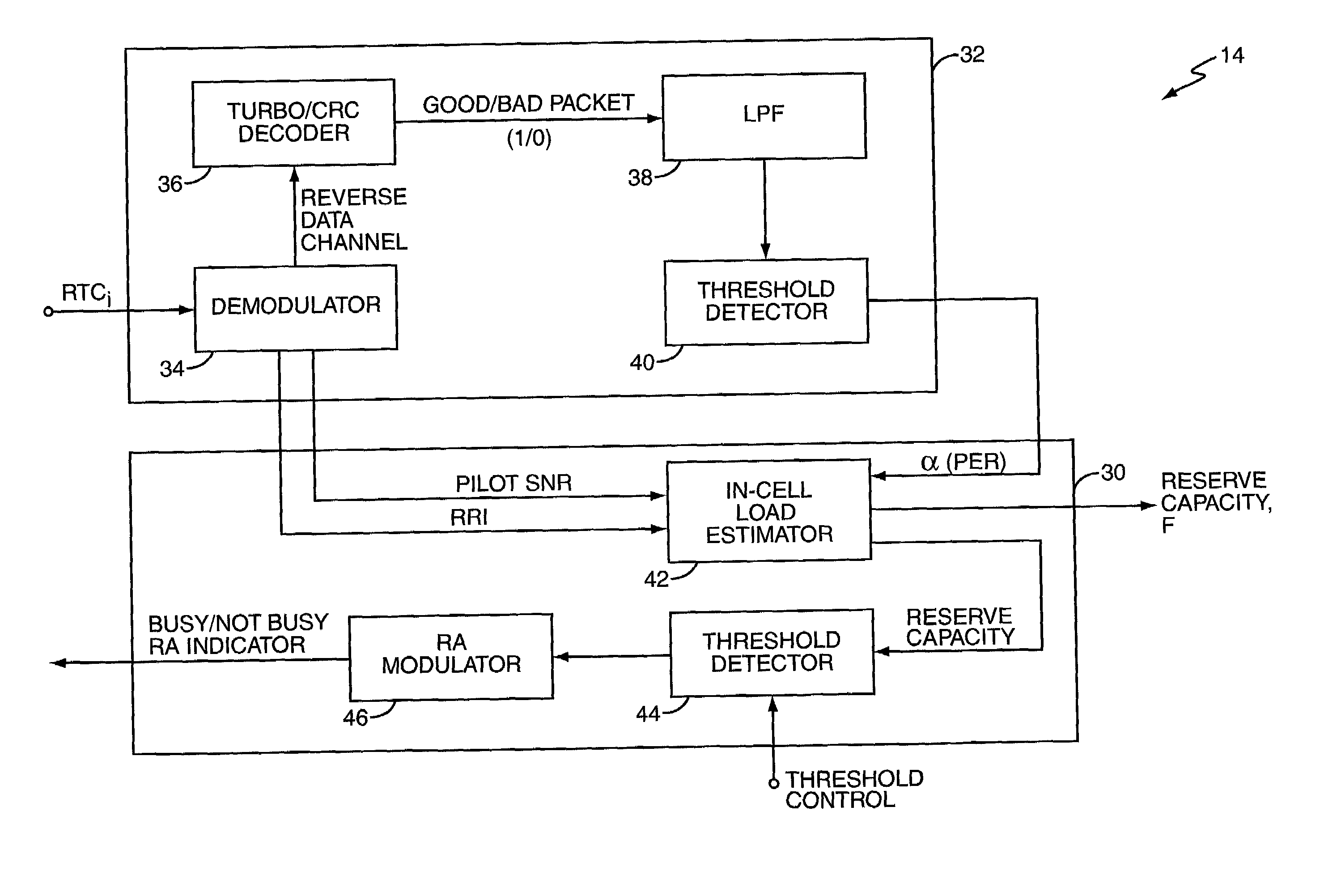
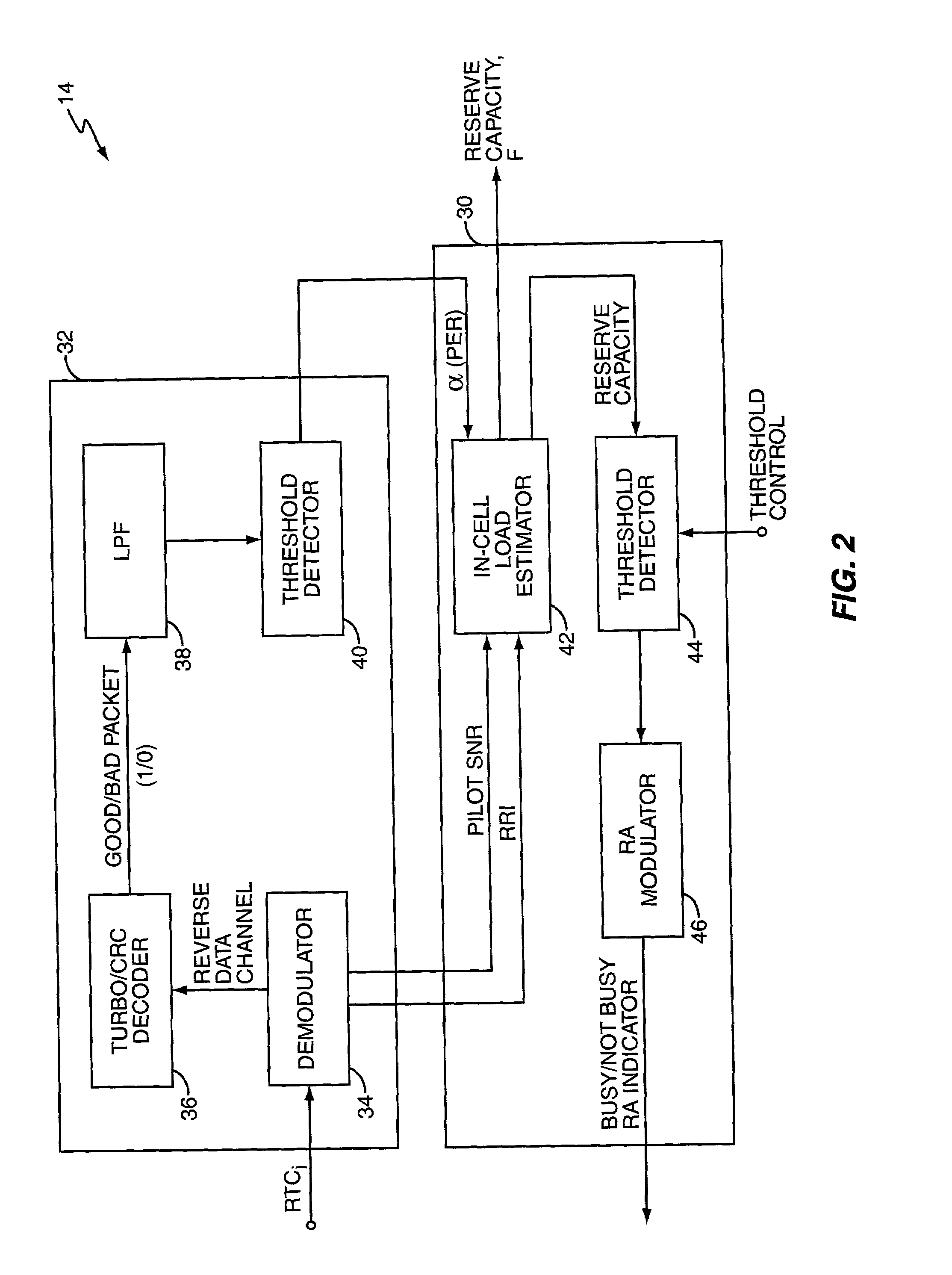
[0013]Preferably, with interdependent control, a central processing site receives sector interference information from a number of sectors and provides feedback information to one or more of those sectors so as to reduce reverse link interference in one or more of the sectors. In some embodiments, the feedback information comprises reverse link reserve capacity threshold settings used by the sectors in determining whether or not to set the reverse link activity indicator to “busy” based on current reverse link capacity utilization. Thus, by sending a reduced threshold value to a given sector, that sector more readily requests the access terminals served by it to reduce their reverse data channel rates in the interest of reducing intersector interference.

Problems solved by technology

In some instances, using a nominal Pilot SNR may introduce error, at least for those access terminals being power controlled by adjacent sectors under soft handoff conditions.

Method used


Image

  • Fast flow control methods for communication networks
  • Fast flow control methods for communication networks
  • Fast flow control methods for communication networks

Examples


Embodiment Construction

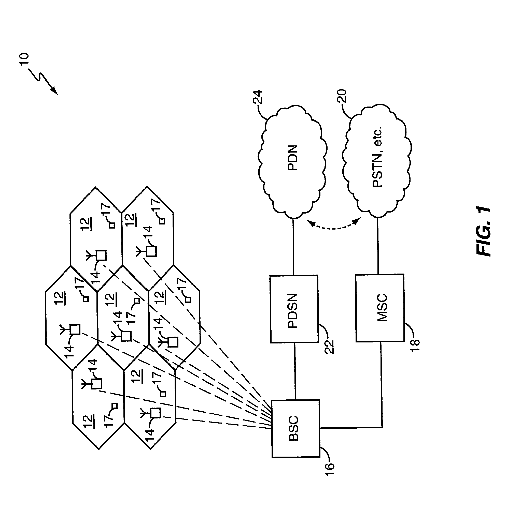
[0017]FIG. 1 illustrates a simplified wireless communication access network generally referred to by the numeral 10, and which may be, for example, a high rate packet data network configured in accordance with the TIA / EIA / IS-856 standard. While this specific air interface standard provides a directly relevant context for discussing the invention, it should be understood that at least some aspects of the present invention have applicability beyond this standard.

[0018]Network 10 as illustrated comprises a plurality of sectors 12, each served by a radio base station (RBS) 14, a base station controller (BSC) 14 supporting the RBSs 12, a mobile switching center (MSC) 18 interfacing the network 10 to one or more external networks 20, and a packet data service node (PDSN) 22 interfacing the network 10 to one or more packet data networks 24. Examples of networks 20 and 24 include but are not limited to the Public Switched Telephone Network (PSTN) and the Internet, respectively.

[0019]Typical...


PUM


Abstract

Reverse link flow control in a high data rate network determines current reverse link data channel rates for access terminals served by a network sector to identify corresponding defined channel gains, which are used to rapidly and reliably estimate total sector interference on the reverse link. Total sector interference indicates reverse link capacity utilization, and when remaining capacity approaches a defined threshold, the sector sets an activity indicator to a busy state indicating reverse link congestion. This action causes at least some access terminals to reduce their reverse link data channel rate. Interference calculation techniques preferably involve baseband digital processing using defined channel gains, permitting rapid evaluation of reverse link capacity and quick, reliable activity indicator updating, which increases reverse link capacity utilization. These techniques may be applied to inter-sector control, wherein the reverse activity indicator status for one sector depends on interference in one or more other sectors.

Description

BACKGROUND OF THE INVENTION[0001]The present invention relates generally to high rate packet data networks for mobile communications and, more particularly, for high rate packet data networks.[0002]The Telecommunications Industry Association (TIA) recently adopted a new specification for high rate packet data services known as TIA / EIA / IS-856 “cdma2000, High Rate Packet Data Air Interface Specification.” Communication networks based on this standard can provide up to 2.4 Mbps in a standard bandwidth 1.25 MHz channel.[0003]In HDR networks, the reverse link traffic channel between the access terminal and the access network is a variable rate channel. The access terminal selects the data rate from among one of five possible data rates and can change the data rate on a packet-by-packet basis without negotiation with the access network. Therefore, the amount of reverse link interference experienced by the base station receiver varies rapidly and by large amounts. A fast flow control metho...

Claims


Application Information

Patent Timeline
IPC IPC(8): G01R31/08H04L12/56
CPCH04L47/10H04L47/14H04W16/14H04W28/08H04W28/10H04W28/22H04W28/0236H04W28/0284H04W8/04
Inventor VANGHI, VIERI
Owner OPTIS WIRELESS TECH LLC
Why Eureka
Eureka Blog
Learn More