
Acousto-optical device based on phonon-induced polaritonic band gaps

a technology of phonons and optical devices, applied in the field of acoustooptical devices based on phonon-induced polaritonic band gaps, can solve the problems of enormous acoustic power which needs to be applied to achieve significant interaction, and achieve the effects of low interaction, fast switching time, and significant performance advantages

Inactive Publication Date: 2007-04-24
UNIV COLLEGE CARDIFF CONSULTANTS LTD +1
View PDF4 Cites 0 Cited by
  • Summary
  • Abstract
  • Description
  • Claims
  • Application Information

AI Technical Summary

Benefits of technology

[0013]This invention can be used to achieve significant performance advantages over previously known or proposed devices. For example, traditional acousto-optic devices achieve a low level of interaction between the acoustic waves and the optical waves, such that the acoustic power which needs to be applied to achieve significant interaction is enormous. This invention allows fast switching time and at relatively low energies of acoustic wave.

Problems solved by technology

For example, traditional acousto-optic devices achieve a low level of interaction between the acoustic waves and the optical waves, such that the acoustic power which needs to be applied to achieve significant interaction is enormous.

Method used


Image

  • Acousto-optical device based on phonon-induced polaritonic band gaps
  • Acousto-optical device based on phonon-induced polaritonic band gaps
  • Acousto-optical device based on phonon-induced polaritonic band gaps

Examples


Embodiment Construction

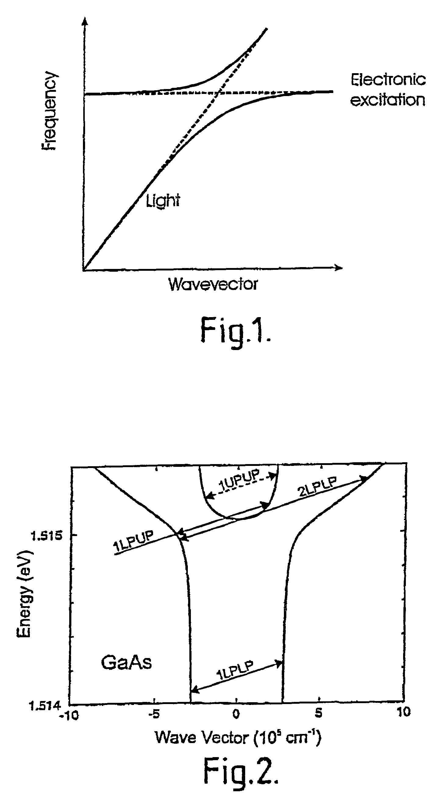
[0027]In the present invention, an alternative to the Stark effect is used in which acoustically driven excitation-polaritons are probed by weak light. Since an acoustically pumped intrinsic Semiconductor remains in its ground electronic state, no many-body effects influence the acoustic Stark effect and weaken the exciton-phonon interaction. A schematic graph of the polariton energy states in bulk updoped Gallium Arsenide (GaAs), driven by Ghz acoustic wave is shown in FIG. 2.

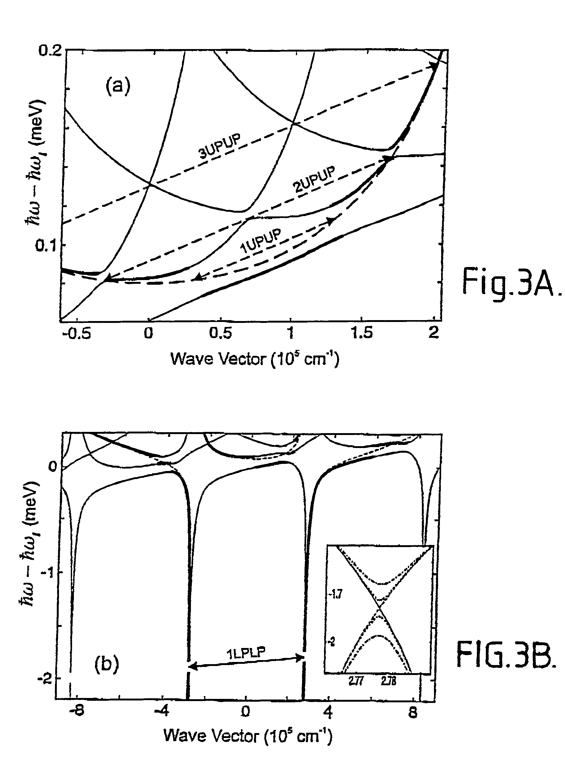
[0028]In the presence of an acoustic wave of wavevector q frequency ω the branches of the polariton dispersion that can undergo degenerate mixing (i.e. the difference frequency and wavevector between the two polaritons is a multiple of the acoustic wave) with the sound wave are strongly changed, while those parts of the dispersion for which the degeneracy condition is not met are hardly changed. Consequently the propagation of light through the sample is modified for specific and tunable frequencies and direct...


PUM


Abstract

The device comprises an optical waveguide and an acoustic wave generating device. The waveguide has an optical band gap and a sharp electronic transition (e.g. an excitonic transition) in the band gap, and the acoustic wave generating device generates acoustic waves within the waveguide. Light passing through the waveguide is of a frequency within the band gap of the waveguide and is nearly resonant with the sharp electronic transition. The wave generating device is arranged to generate acoustic waves so as to induce optical band gas in the polariton spectrum, thereby affecting the transmission of the light passing through the waveguide, the transmission of which is thereby affected.

Description

[0001]This application claims the benefit of International Application No. PCT / GB02 / 04024, which was published in English on Mar. 13, 2003.BACKGROUND OF THE INVENTION[0002]The present invention relates to the use of the Stark effect for acoustically changing the optical properties of a material.[0003]In a solid material, the propagation of light is controlled by the electronic polarisation of the medium. For the simple case of a transparent medium, electronic excitation of the medium can be used to modify the light dispersion properties of the medium by modifying the refractive index. This produces a constant change in the speed of light through the medium. In this way a coherent beam or pulse of acoustic phonons in a material will modify the properties of the material in order to change the refractive index of that material.[0004]When there are electronic resonances at particular energies, the dielectric function has a resonance at the energy of the electronic excitation, and stron...

Claims


Application Information

Patent Timeline
IPC IPC(8): G02F1/335H01S3/00G02F1/01G02F1/017G02F1/125
CPCB82Y20/00G02F1/01708G02F1/125G02F2001/0113G02F1/0113
Inventor LITTLEWOOD, PETER BRENTIVANOV, ALEXANDER L.
Owner UNIV COLLEGE CARDIFF CONSULTANTS LTD
Learn More