Power stack
a technology of power stack and cooling balance, applied in the direction of resistor details, electrical apparatus construction details, lighting and heating apparatus, etc., can solve the problems of power stack cooling balance, etc., to prevent the cooling efficiency from locally deteriorating and excellent cooling balance
- Summary
- Abstract
- Description
- Claims
- Application Information
AI Technical Summary
Benefits of technology
Problems solved by technology
Method used
Image
Examples
first embodiment
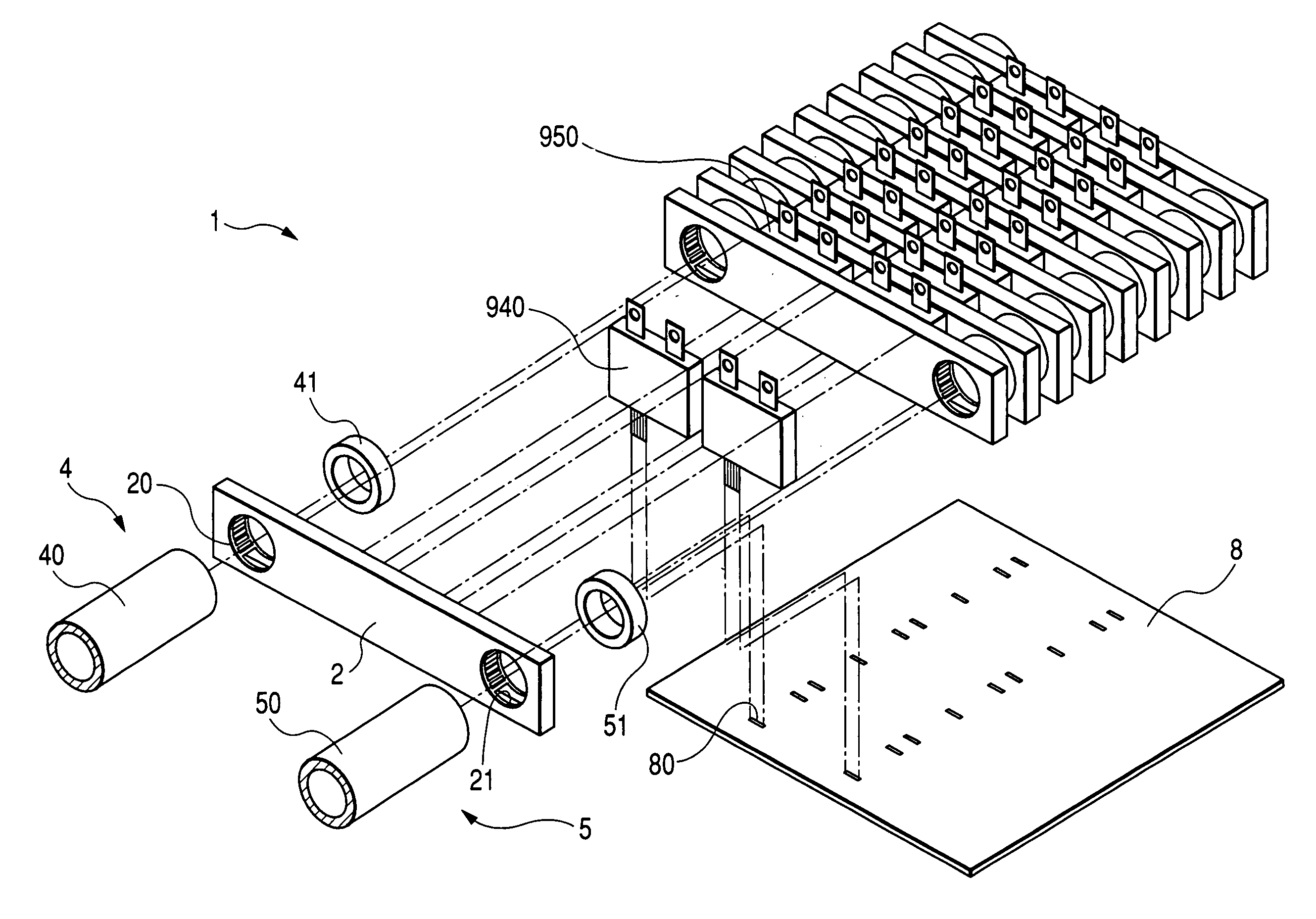
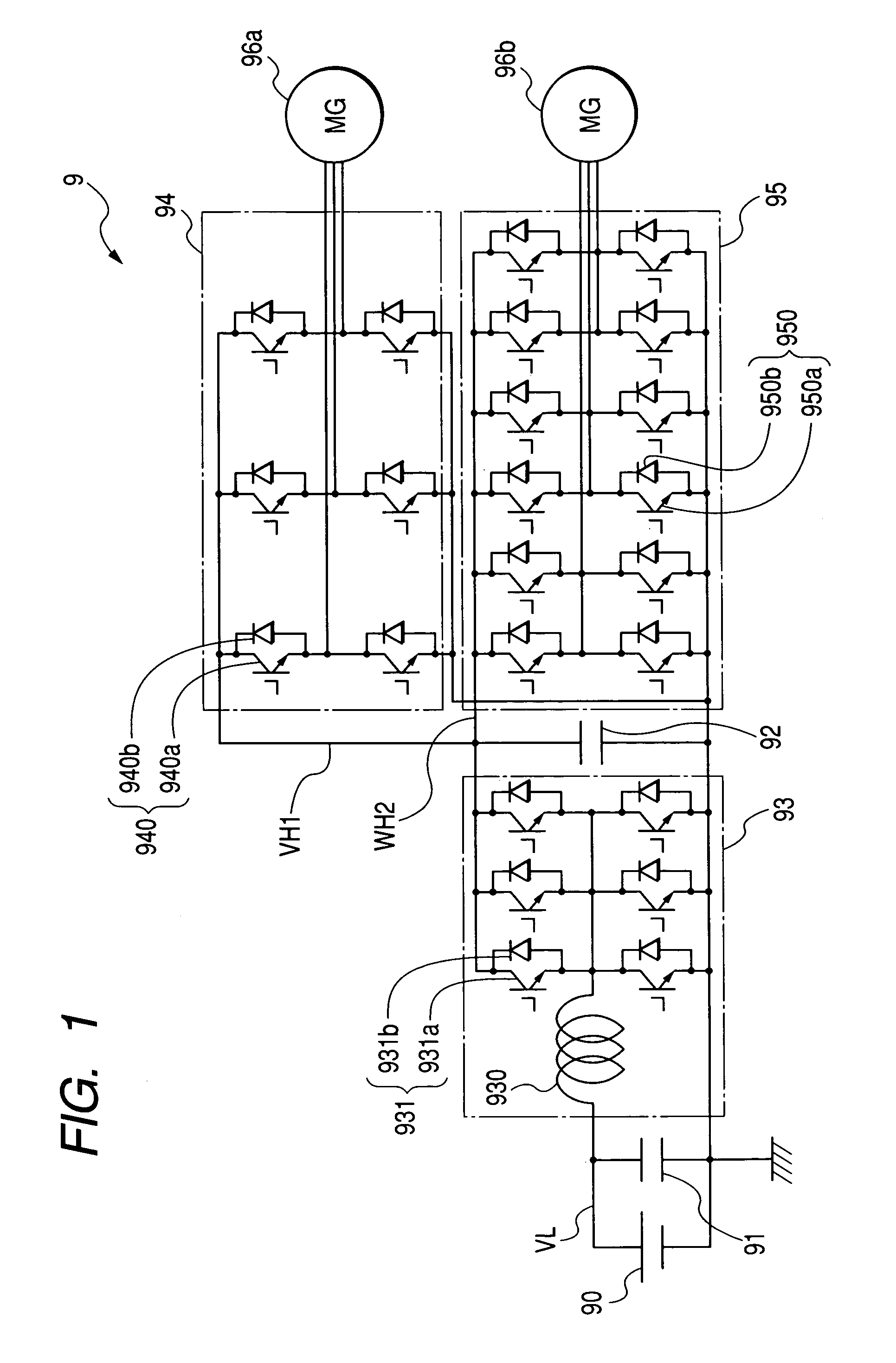
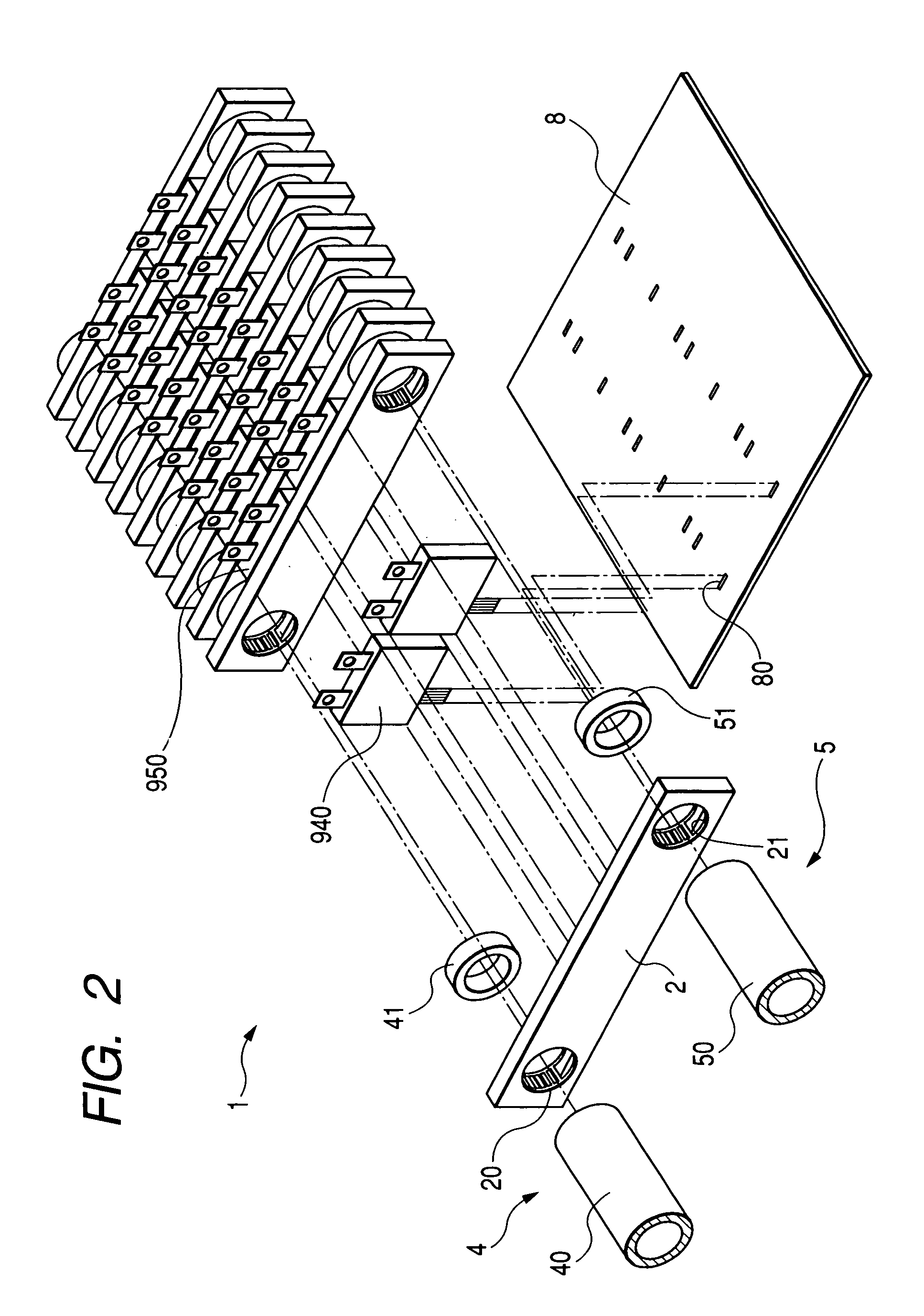
[0056]First, a driving apparatus for a MG (i.e. electric Motor / Generator) will be explained as an example using a power stack of this embodiment. FIG. 1 shows a circuit diagram of this driving apparatus. As shown in the drawing, a driving apparatus 9 includes a battery 90, smoothing capacitors 91 and 92, a DC—DC converter 93, a first inverter circuit 94, and a second inverter circuit 95.
[0057]The DC—DC converter 93 includes an electric reactor 930 and a plurality of converter switching modules 931. One end of the electric reactor 930 is connected to a connecting point of high-potential side converter switching modules 931 and low-potential side converter switching modules 931 which are later described in more detail. The other end of the electric reactor 930 is connected to a high-voltage terminal of the battery 90 via a low-voltage power line VL.
[0058]Each converter switching module 931 consists of an IGBT (i.e. Insulated Gate Bipolar Transistor) 931a and a flywheel diode 931b. Eac...
second embodiment
[0091]The second embodiment is different from the first embodiment in that the electric reactor 930 and the converter switching module 931 shown in FIG. 1 are disposed in the power stack. Hereinafter, this embodiment is explained only about the differences.
[0092]FIG. 8 shows a partly exploded perspective view of a power stack 1a in accordance with this embodiment. The components or portions corresponding to those shown in FIG. 2 are denoted by the same reference numerals. FIG. 9 shows a perspective view of an assembled condition of this power stack 1a. The components or portions corresponding to those shown in FIG. 3 are denoted by the same reference numerals. FIG. 10 shows a cross-sectional view of this power stack 1a. The components or portions corresponding to those shown in FIG. 6 are denoted by the same reference numerals.
[0093]For example, as understood from the comparison between FIG. 10 and FIG. 6, the power stack 1a ; of this embodiment has a main inlet pipe 40 and a main o...
third embodiment
[0101]The third embodiment is different from the second embodiment in the layout of the first switching modules, the second switching modules, and the converter switching modules. Hereinafter, this embodiment is explained only about the differences.
[0102]FIG. 12 shows a schematic plan view of a power stack 1b in accordance with this embodiment. The components or portions corresponding to those shown in FIG. 11 are denoted by the same reference numerals and the same hatching. As shown in the drawing, all of the second switching module 950 (twelve in total) are disposed at the downstream side of the cooling pipes 2 in the flow direction of LLC (refer to FIG. 10). The converter switching modules 931 are disposed at the upstream side of six second switching modules 950 disposed adjacently to the electric reactor 930. Furthermore, the first switching modules 940 are disposed at the upstream side of the remaining six second switching modules 950 disposed far from the electric reactor 930....
PUM
 Abstract
Description
Claims
Application Information
 - R&D
- Intellectual Property
- Life Sciences
- Materials
- Tech Scout
- Unparalleled Data Quality
- Higher Quality Content
- 60% Fewer Hallucinations
Browse by: Latest US Patents, China's latest patents, Technical Efficacy Thesaurus, Application Domain, Technology Topic, Popular Technical Reports.
© 2025 PatSnap. All rights reserved.Legal|Privacy policy|Modern Slavery Act Transparency Statement|Sitemap|About US| Contact US: help@patsnap.com


