
Construction of playing surfaces

a construction and playing surface technology, applied in the field of playing surface construction, can solve the problems of high labor intensity, degrade the performance of the ias, and high cost of aggregate infill spillage at the installation site,

Inactive Publication Date: 2007-03-06
NOTTINGHAMSHIRE SPORTS & SAFETY SYST
View PDF37 Cites 31 Cited by
  • Summary
  • Abstract
  • Description
  • Claims
  • Application Information

AI Technical Summary

Benefits of technology

[0018]It is a principal object of the present invention to avoid or at least reduce the disadvantages referred to, and to provide a multi-layered playing surface structure which can be arranged to provide a highly satisfactory compromise between achieving an adequate critical fall height or impact absorption while maintaining a reasonably firm footing and which still allows modification of the properties of the surface structure in order to construct playing surfaces for different sports and games.
[0020]We have found that such a structure can impart excellent firmness of footing to a playing surface structure without damaging impact absorbing properties. Because the rubber particles are bonded, they are less easy to displace than loose particles, and this allows a better control of the properties of the structure and contributes to a long useful life. Furthermore, we have found that the use of a resin impregnated textile layer can promote stiffening of the surface of the structure thus contributing to a high CFH by reducing impact contact time without necessarily reducing shock absorbency. Because the particulate rubber layer is bound to a textile layer, it can be applied thereto under easily-controlled factory conditions and thus more easily, reliably and reproducibly, and more evenly than under field conditions. It is to be noted, however, that the invention does not exclude the provision of a layer of loose rubber particles beneath the resin impregnated textile layer and bonded layer of particulate rubber should this be desired for some particular reason.
[0021]In the most preferred embodiments of the invention, the resin impregnated textile layer is covered by a surface carpet layer. Sections of such surface carpet layer may be joined together by under-seaming, for example using a hot-melt adhesive tape. Systems for hot-melt under-seaming are well known from the domestic carpet laying industry. We have found that the use of a resin impregnated textile layer in accordance with the invention affords particular advantages in protecting underlying rubber particles from melting or charring when such a hot-melt seaming technique is adopted.

Problems solved by technology

Such compression, movement or contamination of the aggregate and / or sand degrades the performance of the IAS.
These structures have inherent practical and / or logistical problems associated with them such as the need to transport mineral aggregate infill to an installation site.
Additionally, spillage of aggregate infill at an installation site is costly as spilled aggregate infill must be removed from the playing surfaces.
Further to which in order to achieve a consistent surface layer it is necessary to have level aggregate infill and geotextile envelope structures and this requires labour intensive hand finishing.
Attempts have been made to remove the need for aggregate infill by fabricating a playing surface underlay from multiple layers of a random pile material, for example a material known as vertical horizontal angular fibre (VHAF™) but this has limited applications.
However, such systems can suffer from breakdown of resins used in the binding of the rubber over time and their performance can degrade accordingly.
Some playing surface structures must therefore have impact absorbing properties, but at the same time they must not present a surface which is unnaturally soft for a user to walk on with an attendant risk of giving rise to twisting injuries to a user's ankle, or injuring the user in some other manner.
Thus there can be a conflict between the requirements for avoiding impact injuries to users' heads and the requirements for achieving a firm footing.
Sand and stone are inherently shock absorbing but with limitations; this property improves when displacement of the particles occurs, but this is not always a satisfactory outcome as the level of the area may be disturbed, and it is known to provide a shock pad layer.
This is very effective, but can be costly to construct as the granules are spread by hand and it is labour intensive.
Problems with larger loose rubber crumb are that if it is disturbed, it does not self-level the in same way as sand or finer crumb.
Further problems can arise when screeding a thin layer of rubber particles for forming an outdoor playing surface even when they are stabilised by a fibre shock pad.
The application of such particles is disturbed by any adverse weather conditions during the laying: even a light breeze makes it difficult to lay an even layer of rubber particles, and the layer could easily be further disturbed by the positioning of any overlying layer such as a layer of artificial turf without the most careful working procedures.
Unfortunately however, the use of such rubber tiles and mats has certain disadvantages for use in outdoor playing areas in that if the rubber is made thick enough to withstand handling without damage, it on occasion can either be rather impervious to water, in which case the playing area may become waterlogged after rain, or the rubber can swell due to the absorption of rainwater and this tends to disturb the evenness of the playing surface.
Problems can also arise in laying such rolls or tiles in such a manner as to achieve consistent joints between successive elements.

Method used


Image

  • Construction of playing surfaces
  • Construction of playing surfaces

Examples


Embodiment Construction

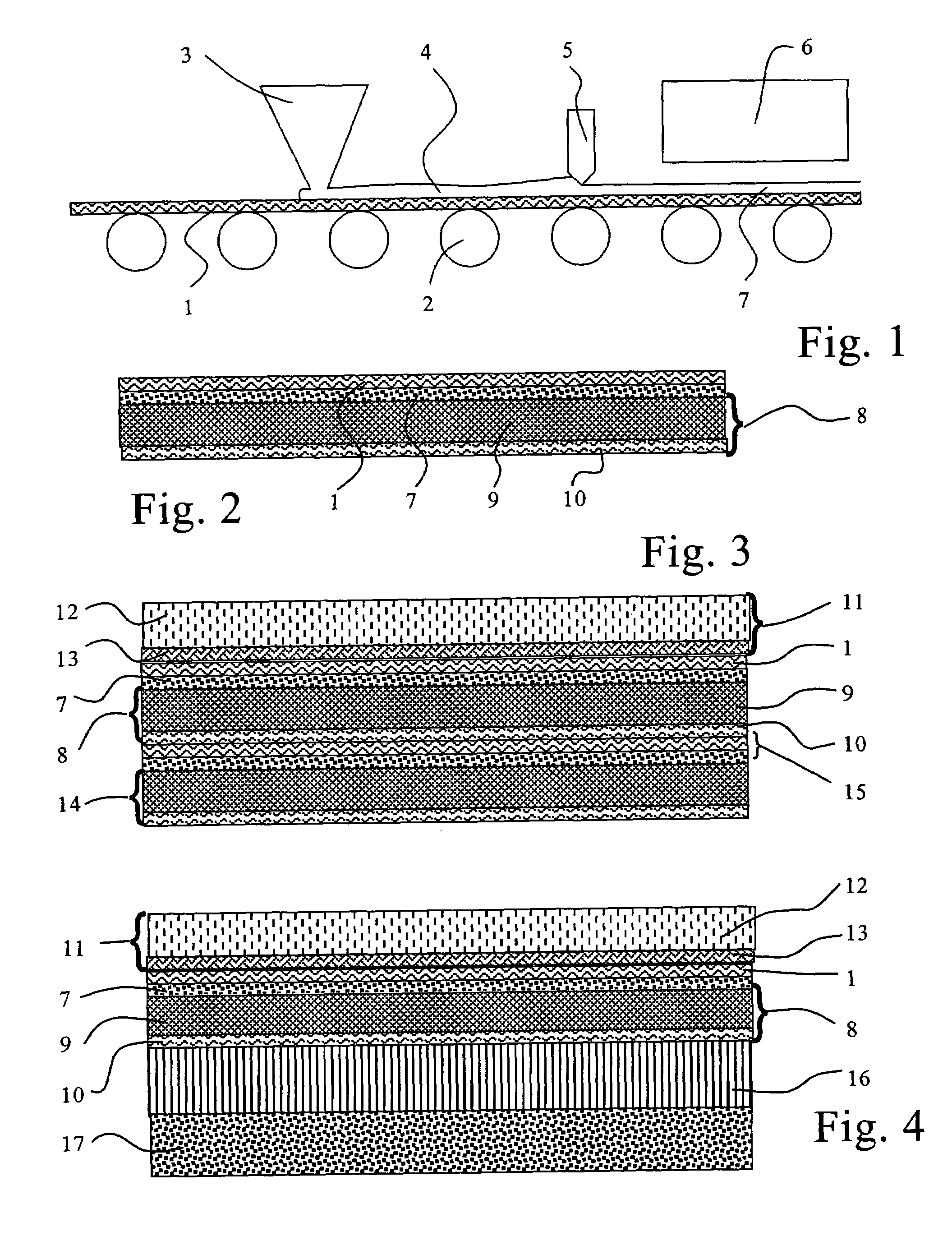
[0033]In FIG. 1 a textile web 1 is carried by a conveyor 2 beneath an applicator 3 where a fluid layer 4 of rubber particles in a resin binder is applied. The web passes beneath a doctor blade 5 where this fluid layer is levelled and its thickness regulated, and thence beneath an appropriate curing device 6 where the fluid layer is cured to become an adherent resin bound layer of rubber particles 7.

[0034]The resin bonded layer of rubber particles is suitably up to 10 mm in thickness, containing rubber in amounts of 0.5 to 4 kg / m2.

[0035]In FIG. 2, a playing surface structure includes a resin impregnated textile layer 1 having a resin bonded layer of particulate rubber 7 adherent to its undersurface and overlying a fibrous random pile mat 8 incorporating a random pile layer 9 and a relatively compact, resin impregnated backing layer 10.

[0036]In FIG. 3, the resin impregnated textile layer of FIG. 1 is covered by a surface carpet layer 11 having a pile 12 and a backing 13. The surface c...


PUM

PropertyMeasurementUnit
Thicknessaaaaaaaaaa
Lengthaaaaaaaaaa
Surface structureaaaaaaaaaa

Abstract

A playing surface structure includes a resin impregnated textile layer (1) having a resin bonded layer of particulate rubber (7) adherent to its undersurface and overlying a fibrous random pile mat (8) incorporating a random pile layer (9) and a relatively compact, resin impregnated backing layer (10).

Description

CROSS REFERENCE TO RELATED APPLICATIONS[0001]The present application claims benefit to Great Britain Application No. GB 0307671.8 filed Apr. 3, 2003.TECHNICAL FIELD OF THE INVENTION[0002]This invention relates to the construction of playing surfaces, in particular games playing surfaces, and the invention has particular, but not exclusive, reference to surfaces for playing outdoor games and sports including sports pitches and children's playgrounds.BACKGROUND OF THE INVENTION[0003]It is known to construct artificial games-playing surfaces over a substrate, for example of sand or gravel by applying a geotextile and a top layer of artificial turf to simulate natural performance characteristics. The use of particulate materials other than natural aggregates or combinations of both has also been proposed.[0004]Desirable performance characteristics of the construction may vary widely depending on the primary intended use of the surface.[0005]Impact absorbing surfaces (IAS) for playground...

Claims


Application Information

Patent Timeline
IPC IPC(8): B32B33/00B32B3/02B32B5/12E01C13/08
CPCE01C13/08Y10T428/23986Y10T428/23979Y10T428/23921Y10T428/23914
Inventor FOXON, STEPHEN ALAN
Owner NOTTINGHAMSHIRE SPORTS & SAFETY SYST
Learn More