
Metal mold device for blow molding

Inactive Publication Date: 2007-02-06
MINORU KASEI KK
View PDF14 Cites 4 Cited by
  • Summary
  • Abstract
  • Description
  • Claims
  • Application Information

AI Technical Summary

Benefits of technology

[0009]The present invention is made in light of the above-described problems in conventional heating and cooling means; and the object of the present invention is to provide a metal mold device for blow molding in which sufficiently rapid heating and sufficiently rapid cooling of the metal mold are accomplished, no irregularity occurs in the metal mold temperature, and the amount of energy that is consumed can be small.
[0012]In the above-described metal mold device for blow molding, either heating or cooling alone of the metal mold can be performed, or a cycle of heating and cooling can be repeated. High transfer properties can be obtained by supplying a heating fluid (e.g., high-temperature water or high-temperature steam) prior to the supply of the parison so that the metal mold is heated and by causing the outside surfaces of the parison in a softened state to contact the heated inside surfaces of the metal mold. Meanwhile, if the heated metal mold is cooled by supplying a cooling fluid (e.g., cooling water) after the parison has contacted the inside surfaces of the metal mold, the blow-molded article can be quickly cooled and hardened, so that the molded article can be quickly removed from the metal mold. Accordingly, the cycle time can be shortened so that high-speed molding is accomplished. Furthermore, by way of alternately performing heating and cooling, high transfer properties and high-speed molding are both achieved.

Problems solved by technology

Furthermore, following this contact, the metal mold is forcibly cooled by the cooling means, so that the blow-molded body can be quickly hardened and removed, thus shortening the cycle time.
(1) Means in which heating and cooling of the metal mold are accomplished by laying pipes along the back surfaces of the metal mold, and alternately circulating a heating fluid (e.g., high-temperature water or high-temperature steam) and a cooling fluid (e.g., cooling water) through these pipes. In this case, it is difficult to lay pipes so that these pipes adhere tightly to the back surfaces of the metal mold along the entire length of the pipes; furthermore, since the pipes are round, the contact area with the metal mold is also small. Accordingly, the heat exchange efficiency is poor, and the heating and cooling rates cannot increase.
(2) Means in which pipes (consisting of a metal whose melting point is higher than that of the metal mold) are disposed inside the casting mold when the metal mold is cast, so that pipes are cast inside the walls of the metal mold. In this case, gaps are formed between the cast pipes and the metal mold during use. Furthermore, since the pipes are round, the contact area with the metal mold is small in relation to the cross-sectional area of the pipes. As a result, the heat exchange efficiency is poor; and in addition, since the thickness of the metal mold must be increased, the thermal capacity of the metal mold increases, and the heating and cooling rates do not increase.
(3) Means in which drill holes are formed vertically and horizontally inside the walls of the metal mold from the back surfaces of the metal mold, and are caused to communicate with each other, and a heating or cooling fluid is circulated through these holes. In this case, the advantage of direct contact of the heating or cooling fluid with the metal mold is obtained. However, since the drill holes are round so that the contact area between the metal mold and the fluid is small in relation to the cross-sectional area, the heat exchange efficiency is poor. In addition, since the thickness of the metal mold must be large, the thermal capacity of the metal mold is large. Moreover, since the drill holes can only be formed in a rectilinear configuration, it may be impossible (depending on the shape of the metal mold) to form the required number of holes, so that the heating and cooling rates cannot increase.
(4) Means in which spaces are formed on the back surface sides of the metal mold, and the metal mold is heated or cooled by circulating a heating or cooling fluid through these spaces (see Japanese Patent Application Laid-Open (Kokai) No. 9-164583). In this case, since the heating or cooling fluid is circulated through large spaces, a large quantity of fluid is required, and the thermal capacity of the metal mold as a whole surrounding the spaces is also large; as a result, a large quantity of energy is consumed. In addition, since the fluid loiters (has a slow flow velocity) inside the spaces, the heat exchange efficiency is poor, and the heating and cooling rates cannot increase.
(5) Means in which thin plate bodies that form a cavity are disposed on the joining surfaces of the metal mold main body, and a narrow gap is formed between the metal mold main body and the thin plate bodies, and cooling of the metal mold is accomplished by causing a cooling medium to flow through this gap (see Japanese Patent Application Laid-Open (Laid-Open (Kokai)) No. 10-235722). In this case, though rapid cooling of the thin plate bodies that form the cavity is possible, non-uniform flow of the cooling medium occurs inside the gap, and the cooling rate varies according to the position, thus tending to cause irregularities in the metal mold temperature.

Method used


Image

  • Metal mold device for blow molding
  • Metal mold device for blow molding
  • Metal mold device for blow molding

Examples


Embodiment Construction

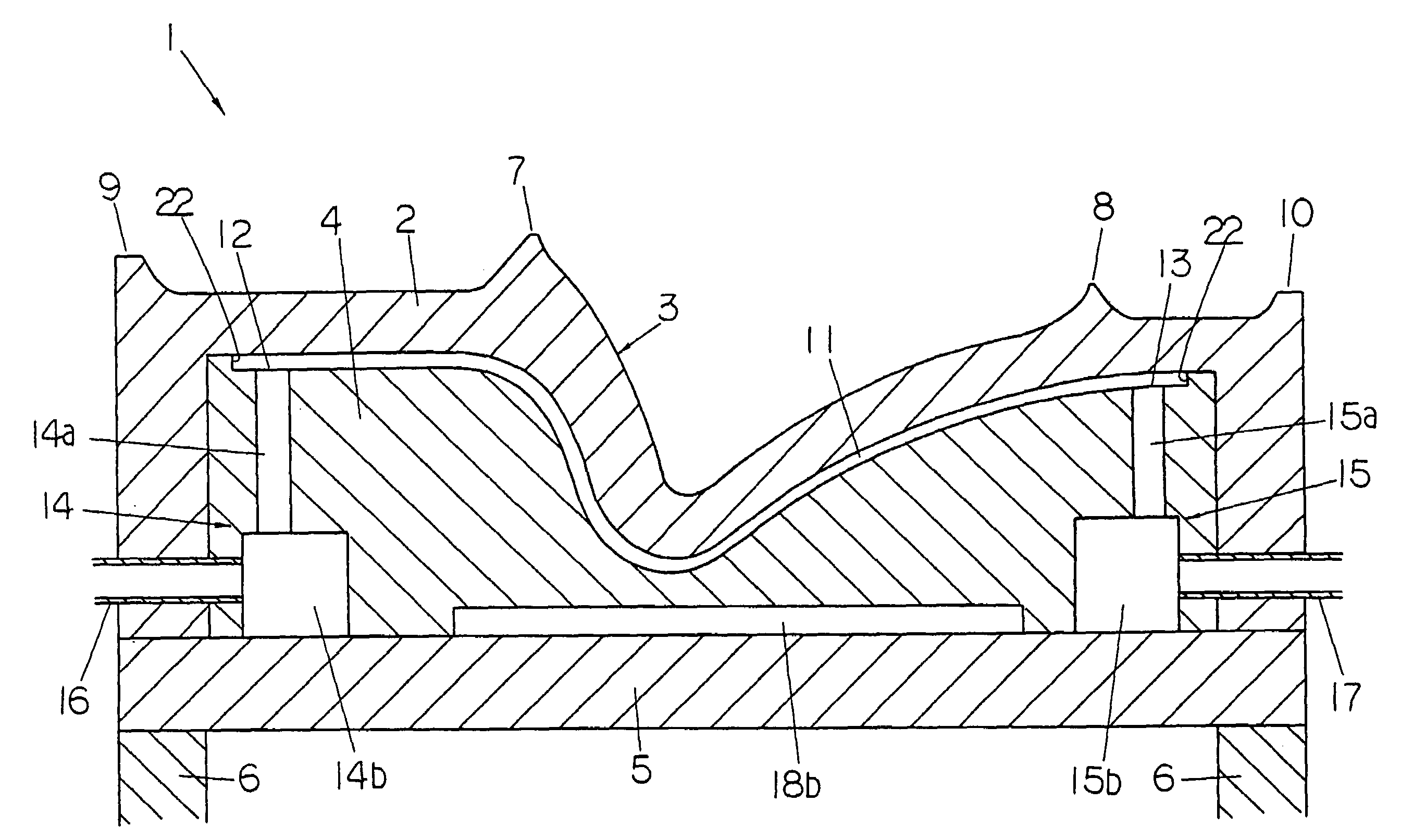
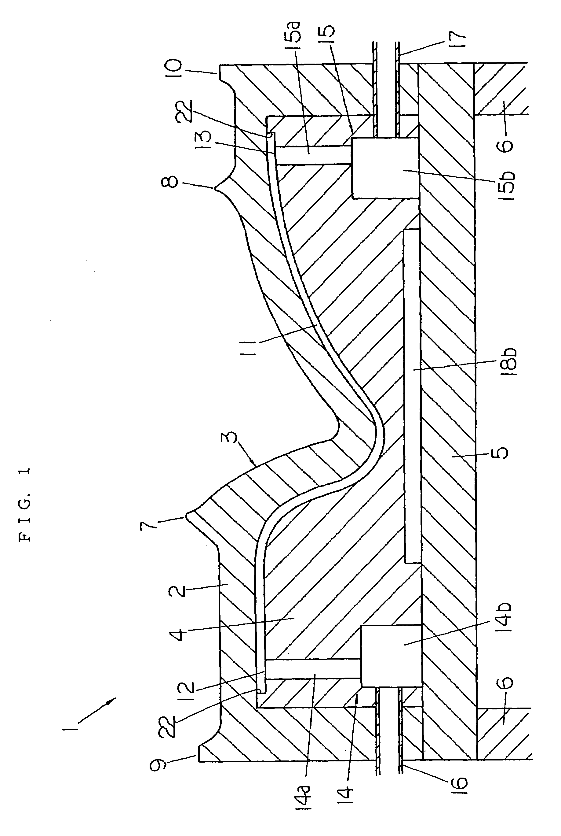
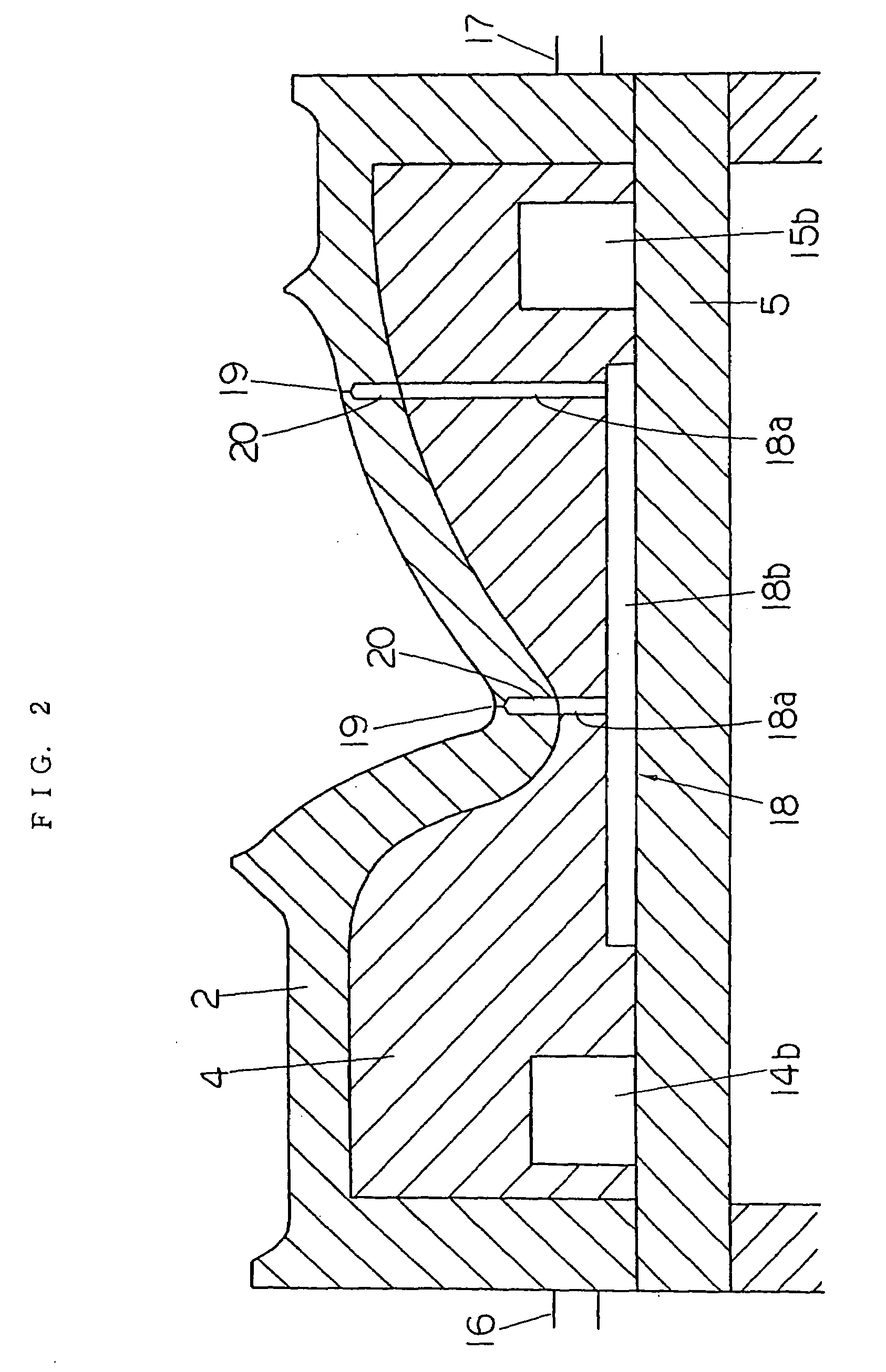
[0020]The metal mold device for blow molding according to the present invention will be described below with reference to the schematic diagrams shown in FIGS. 1 through 4.

[0021]The metal mold device 1 for blow molding shown in FIG. 1 (only one side is shown) comprises a metal mold 2 which has a cavity portion 3, a back-up member 4 which is disposed inside the metal mold structural body and on the back surface side of the metal mold 2, a back plate 5 which supports the back of the metal mold 2, and reinforcing members 6 which support the back plate 5 and are connected to an opening-and-closing mechanism, etc. The above-described cavity portion 3 is in the area surrounded by pinch-off portions 7 and 8, and contact portions 9 and 10 are formed on the left and right ends of the metal mold 2. The pinch-off portions 7 and 8 are the areas where cutting of the parison is performed. The contact portions 9 and 10 contact the contact portions of a metal mold (not shown in the drawings; a cavi...


PUM

PropertyMeasurementUnit
Widthaaaaaaaaaa
Widthaaaaaaaaaa
Depthaaaaaaaaaa

Abstract

Fluid flow grooves (11) with a flat cross section being formed between the back surface of a metal mold (2) for blow molding and a back-up member (4) which adheres tightly to this back surface. A plurality of these fluid flow grooves (11) are provided, and these fluid flow grooves are disposed densely in parallel with partition walls (21) interposed between the grooves. Fluid inlets (12) and outlets (13) are formed in the respective fluid flow grooves (11). A heating fluid or cooling fluid enters the respective fluid flow grooves (11) via the inlets (12) from a fluid supply manifold (14). The fluid flows out of the outlets (13), enters a fluid discharge manifold (15), and is discharged to the outside. Rapid heating and rapid cooling of the metal mold (2) are performed, no irregularity occurs in temperature, and the cycle time can be shortened, so that a metal mold device for blow molding in which the energy consumption is small can be obtained.

Description

TECHNICAL FIELD[0001]The present invention relates to a metal mold device which is for blow molding and is equipped with heating and / or cooling means.BACKGROUND ART[0002]In cases where high transfer properties and high-speed molding are required in blow molding, heating and cooling means are installed in the metal mold. More specifically, the metal mold is heated by the heating means before the parison is supplied, and the outer surfaces of the parison in a softened state are caused to contact the inside surfaces of the heated mold so that high transfer properties are obtained. Furthermore, following this contact, the metal mold is forcibly cooled by the cooling means, so that the blow-molded body can be quickly hardened and removed, thus shortening the cycle time. If high-speed heating and high-speed cooling of the metal mold are possible, then the cycle time can be shortened.[0003]The following means are known as the above-described heating and cooling means:[0004](1) Means in whi...

Claims


Application Information

Patent Timeline
IPC IPC(8): B29C49/64B29C33/04B29C33/56B29C35/04B29C35/16B29C49/04B29C49/48B29C49/50
CPCB29C33/04B29C33/565B29C49/4823B29C35/04B29C49/04B29L2031/3058B29C49/50B29C2035/1616B29C2793/00
Inventor NISHIOKA, KAZUMICHIFUKUHARA, NAOSHIGETACHIBANA, NAOAKI
Owner MINORU KASEI KK
Learn More