
Pulsed plasma processing method and apparatus

a plasma assisted substrate and processing method technology, applied in the field of plasma assisted substrate processing, can solve the problems of inability to efficiently remove volatile etch products, inability to make efficient use of reactive gases, and inability to control reaction chemistry and ion bombardment in known chamber configurations

Inactive Publication Date: 2007-01-23
TOKYO ELECTRON LTD
View PDF21 Cites 266 Cited by
  • Summary
  • Abstract
  • Description
  • Claims
  • Application Information

AI Technical Summary

Benefits of technology

[0024]It is a primary object of the present invention to eliminate a number of limitations inherent in known wafer processing procedures based on inductively coupled plasma (ICP) technology.
[0025]A more specific object of the invention is enable independent control of process parameters in a direction to optimize different process stages for the purpose of improving etch selectivity and side wall profile.
[0026]A further specific object of the invention is to utilize pulsed gas and pulsed RF modulation to improve gas use efficiency and thus reduce pump speed requirements.

Problems solved by technology

In fact, temporal modulation of process parameters on a time scale that is small relative to the process time yet large compared with the RF period is limited to a few select areas of research.
However, known wafer processing technologies based on inductively coupled plasma (ICP) technology lack independent control of reaction chemistry and ion bombardment.
Furthermore, known chamber configurations are incapable of making efficient use of reactive gases, or of efficiently removing volatile etch products.

Method used


Image

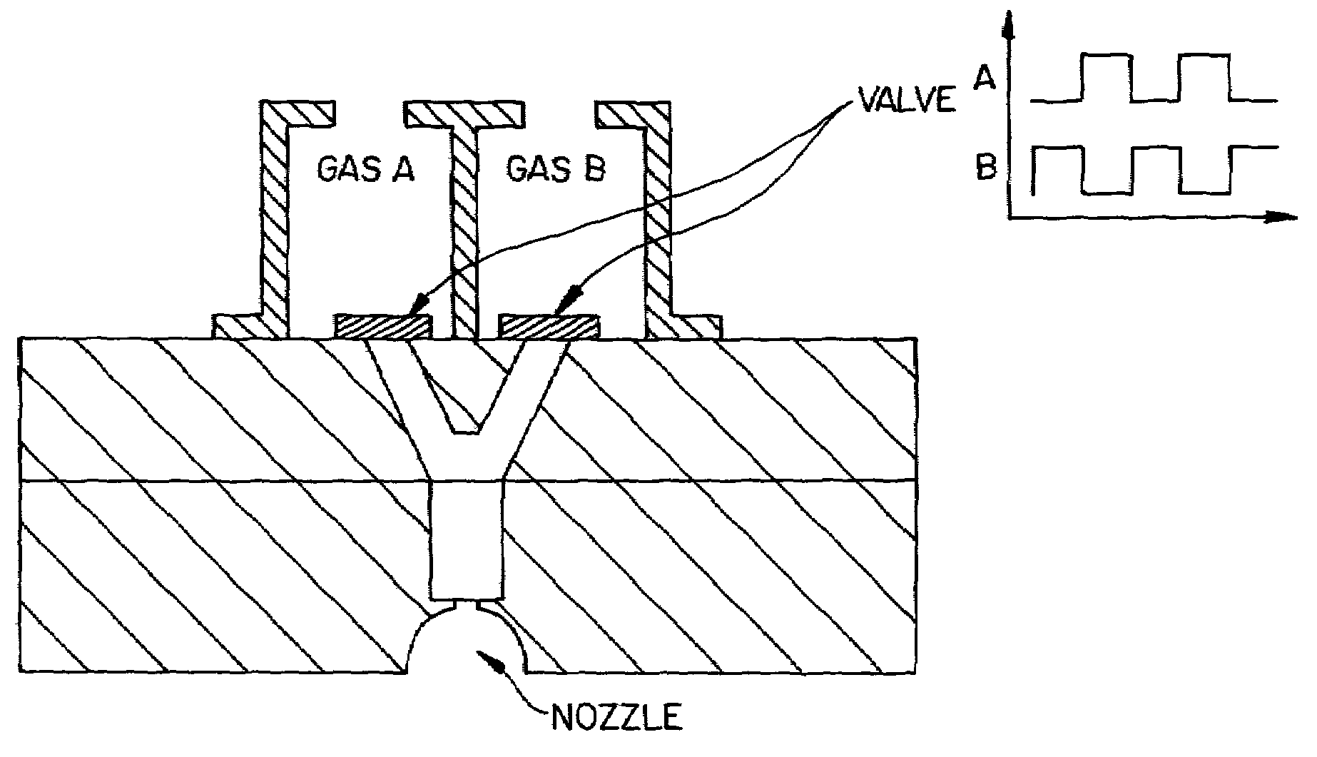
  • Pulsed plasma processing method and apparatus
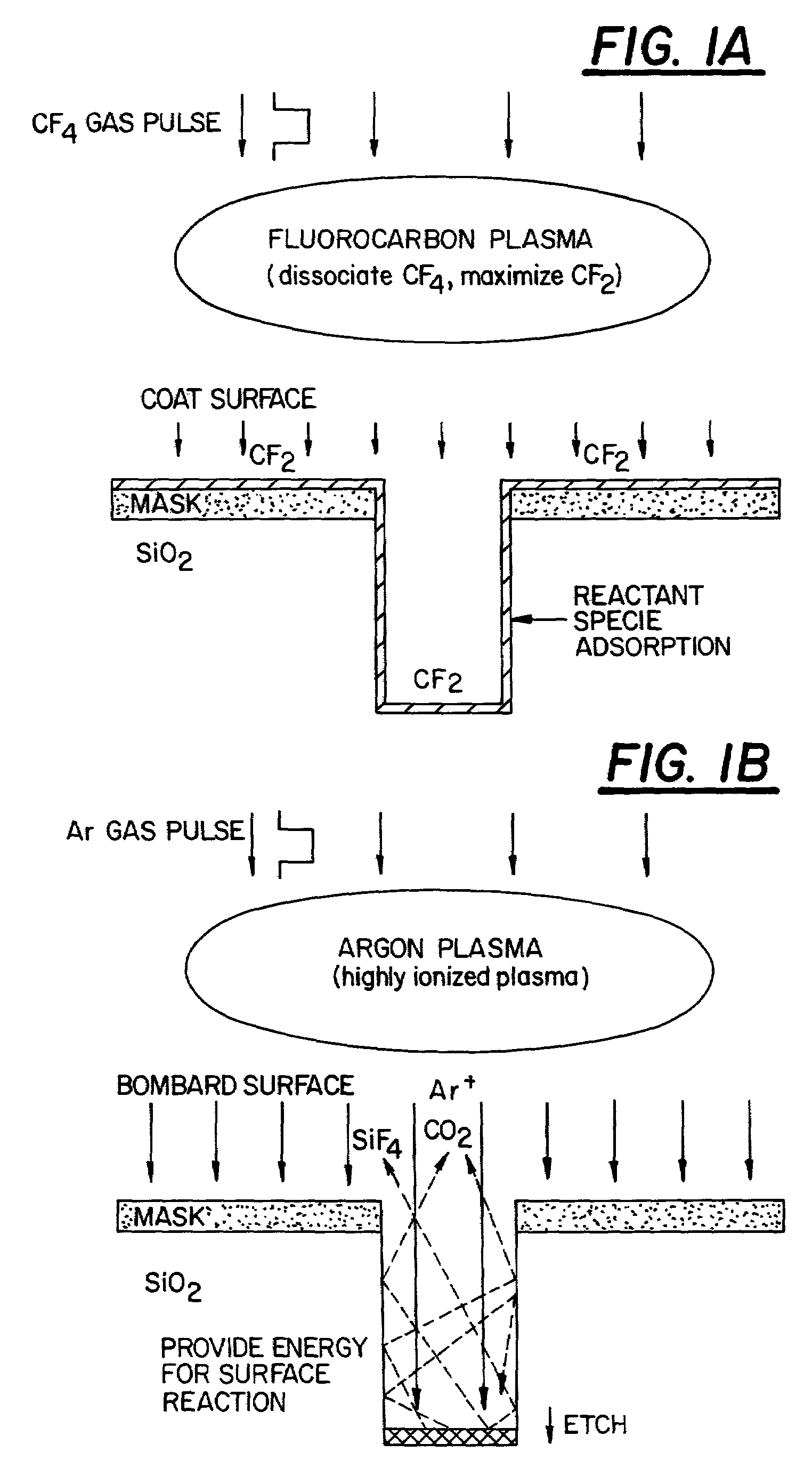
  • Pulsed plasma processing method and apparatus
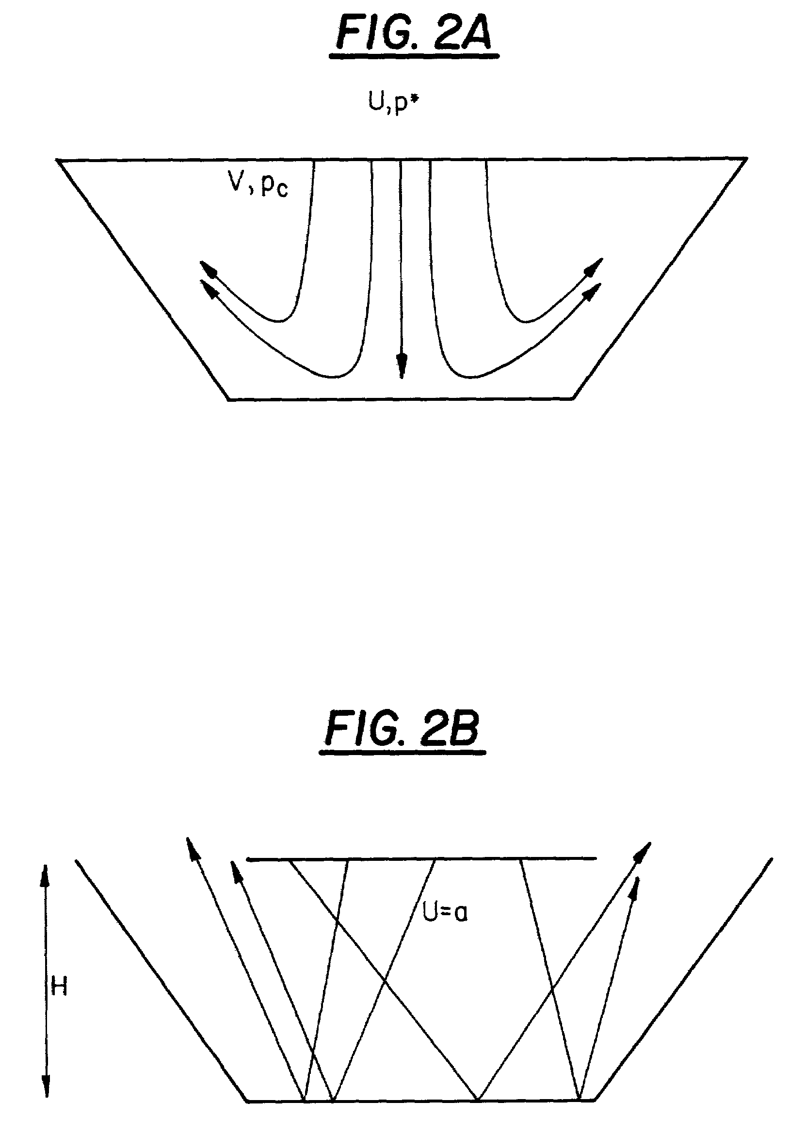
  • Pulsed plasma processing method and apparatus

Examples


second embodiment

[0129]A second embodiment can employ several smaller turbo-molecular pumps above the intermediate vacuum chamber.

third embodiment

[0130]A third embodiment can have the form disclosed in copending Provisional U.S. Patent Application No. 60 / 114,453, filed on Dec. 30, 1998, entitled PLASMA PUMP, the disclosure of which is incorporated herein by reference, and in the previously-cited International Application PCT / US99 / 12827. This embodiment provides improved pumping efficiency and space usage.

[0131]FIG. 18 is a view similar to that of FIG. 17A, illustrating a further practical embodiment of a PME reactor according to the invention. Many of the components of the reactor shown in FIG. 18 are identical to those shown in FIGS. 17A, 17B and 17C. Those components are identified by the same reference numerals as employed in FIGS. 17A, 17B and 17C and will not be described again.

[0132]As in the case of the embodiment of FIG. 17, the components of the embodiments shown in FIG. 18 are carried by a support frame which is mounted on rollers to allow the reactor to be brought to any desired location within a manufacturing faci...


PUM

PropertyMeasurementUnit
Timeaaaaaaaaaa
Timeaaaaaaaaaa
Pressureaaaaaaaaaa

Abstract

In a method for performing a plasma-assisted treatment on a substrate in a reactor chamber by: introducing at least one process gas into the reactor chamber; and creating a plasma within the reactor chamber by establishing an RF electromagnetic field within the chamber and allowing the field to interact with the process gas, the electromagnetic field is controlled to have an energy level which varies cyclically between at least two values each sufficient to maintain the plasma, such that each energy level value is associated with performance of a respectively different treatment process on the substrate.

Description

[0001]This is a Continuation Application of International Application No. PCT / US00 / 21667, which was filed on Aug. 9, 2000, which is based on U.S. Provisional Application No. 60 / 149,177, which was filed on Aug. 17, 1999. The contents of both of these applications are incorporated by reference in their entirety.BACKGROUND OF THE INVENTION[0002]1. Field of Invention[0003]The present invention relates to a mode of plasma assisted substrate processing in which a gaseous species is ionized, dissociated, or otherwise modified in a plasma and the modified species or a component thereof is caused to strike the substrate.[0004]2. Prior Art[0005]Over the past several decades, plasma assisted substrate processing has found increasing acceptance in a variety of industries, particularly within the semiconductor industry where the fundamental process steps include reactive ion etching (RIE), plasma assisted chemical vapor deposition (CVD), sputtering, reactive sputtering, and ion assisted physical...

Claims


Application Information

Patent Timeline
IPC IPC(8): C23C16/00H01L21/306F16K31/02B01J19/08C23C16/505C23C16/515C23C16/517H01J37/32H01L21/302H01L21/3065H01L21/311
CPCH01J37/32082H01L21/31116H01J37/3244H01J37/32137C23C16/44
Inventor JOHNSON, WAYNE L.STRANG, ERIC J.
Owner TOKYO ELECTRON LTD
Learn More