
Situ finishing aid control

a technology of finishing aid and control device, which is applied in the direction of manufacturing tools, grinding machine components, lapping machines, etc., can solve the problems of reducing the perfection of the surface, reducing the friction coefficient(s) of the operative finishing interface, and other unwanted surface damage, so as to improve the finishing effect, reduce defects, and change the friction coefficient

Inactive Publication Date: 2007-01-02
SEMCON TECH
View PDF80 Cites 21 Cited by
  • Summary
  • Abstract
  • Description
  • Claims
  • Application Information

AI Technical Summary

Benefits of technology

[0006]It is an advantage of this invention to reduce the harshness of abrasive finishing on the workpiece surface during finishing. It is an advantage of this invention to reduce unwanted scratching or other unwanted surface damage on the workpiece surface during finishing. It is further an advantage of this invention to reduce the coefficient(s) of friction during finishing a workpiece to help reduce unwanted surface damage. It is an advantage of this invention to reduce unwanted damage to the workpiece surface when during finishing with a fixed abrasive finishing element an abrasive particle unexpectedly breaks away from their surface. It is an advantage of the invention to reduce unwanted damage to the workpiece surface when an abrasive workpiece particle breaks away workpiece surface during finishing. It is an advantage to use tracking the workpiece as it undergoes multiple finishing steps to update and change a preferred model used for advanced real time control to reduce unwanted workpiece defects. It is further an advantage of this invention to help improve yield for workpieces having extremely close tolerances such as semiconductor wafers.

Problems solved by technology

Abrasive finishing of sensitive microelectronic surfaces can suffer from overly harsh finishing on a workpiece causing unwanted scratching or other unwanted surface damage thus reducing the perfection of the surface.
Further, finishing pad finishing surface can suffer from having a higher than necessary coefficient of friction when finishing a workpiece causing higher than desired coefficient(s) of friction in the operative finishing interface.
This higher than necessary coefficient of friction can lead to other unwanted surface damage.
Further, fixed abrasive finishing pads can have abrasive particles unexpectedly break away from their surface during finishing and these broken away abrasive particles can scratch or damage the workpiece surface.
Still further, during finishing a particle can break away from the workpiece surface forming a workpiece abrasive particle which can scratch or damage the workpiece surface.
These unwanted effects are particularly important and deleterious to yield when manufacturing electronic wafers which require extremely close tolerances in required planarity and feature sizes.

Method used


Image

  • Situ finishing aid control
  • Situ finishing aid control
  • Situ finishing aid control

Examples


Embodiment Construction

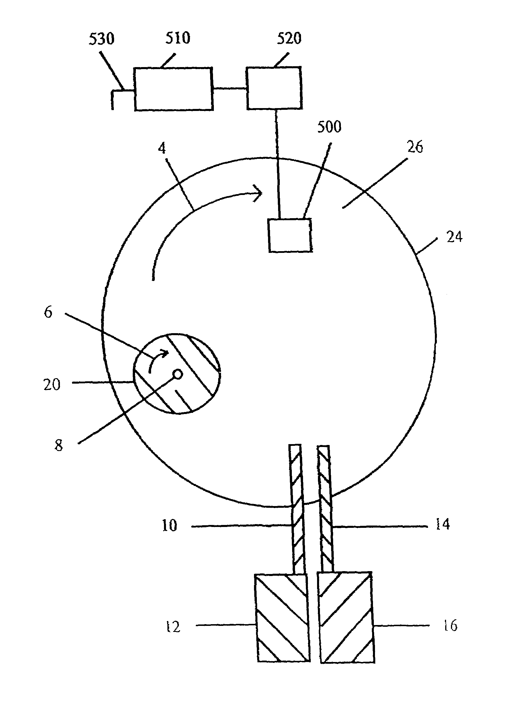
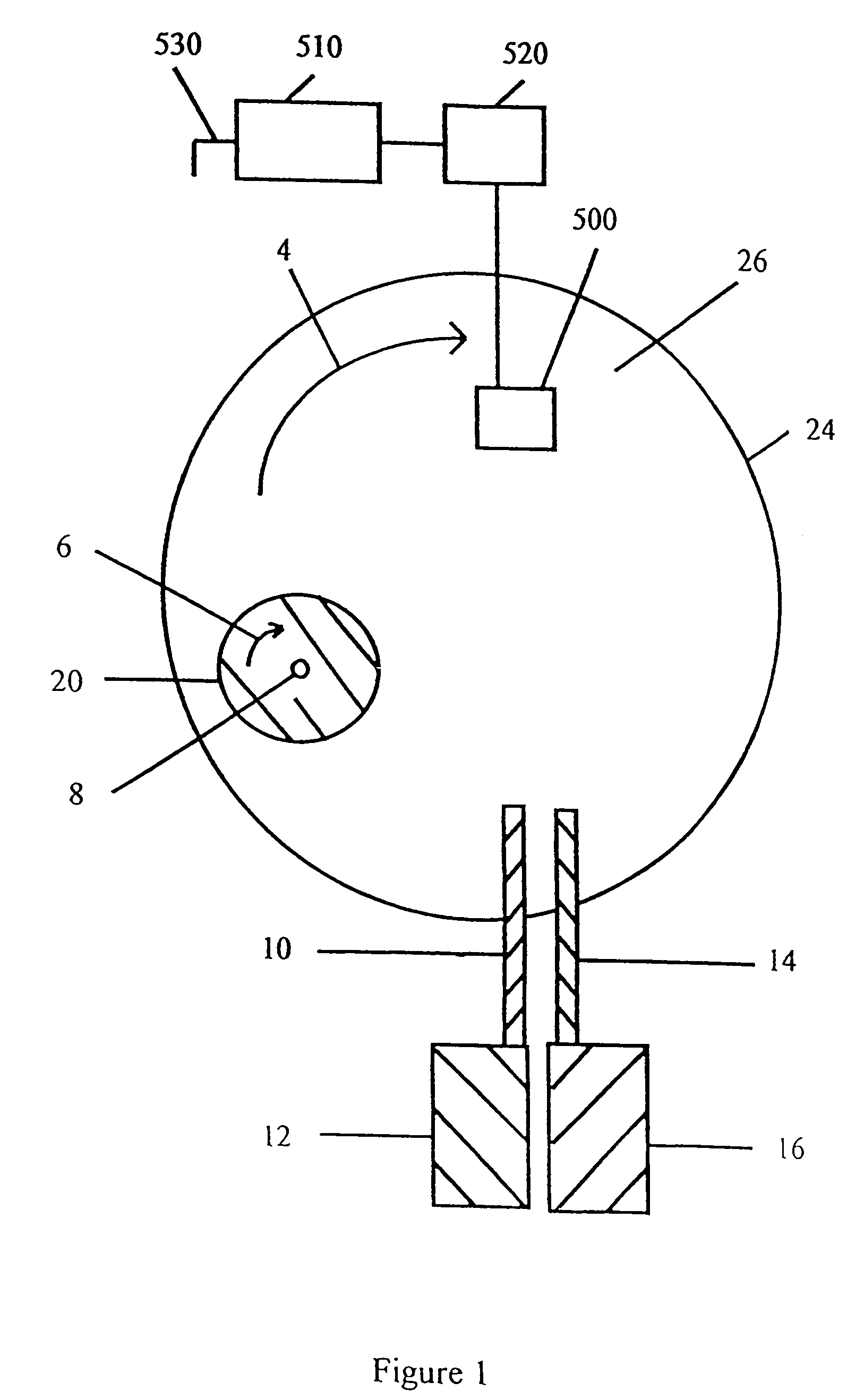
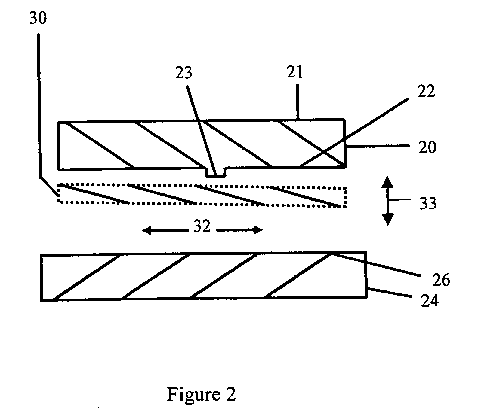
[0071]The book Chemical Mechanical Planarization of Microelectric Materials by Steigerwald, J. M. et al published by John Wiley & Sons, ISBN 0471138274 generally describes chemical mechanical finishing and is included herein by reference in its entirety for general background. In chemical mechanical finishing the workpiece is generally separated from the finishing element by a polishing slurry. The workpiece surface being finished is in parallel motion with finishing element finishing surface disposed towards the workpiece surface being finished. The abrasive particles such as that found in a polishing slurry interposed between these surfaces generally aid in finishing the workpiece.

[0072]Discussion of some of the terms useful to aid in understanding this invention are now presented. Finishing is a term used herein for both planarizing and polishing. Planarizing is the process of making a surface which has raised surface perturbations or cupped lower areas into a planar surface and ...


PUM

PropertyMeasurementUnit
Diameteraaaaaaaaaa
Timeaaaaaaaaaa
Frictionaaaaaaaaaa

Abstract

A method of using finishing aids for advanced finishing control is described. A finishing surface is used generally to induce frictional wear. The finishing aids with preferred in situ control can improve control of the coefficient of friction, the tangential force of friction, a finishing rate, a regional finishing rate(s), a differential finishing rate, and help reduce unwanted defects. A finishing aid can reduce friction. A lubricant is an illustrative finishing aid. The method uses finishing control subsystem having a multiplicity of operative process sensors along with tracked information to improve in situ control of finishing. Differential finishing rate methods are described to differentially finish semiconductor wafers. Differential lubricating film methods are described to differentially finish semiconductor wafers. Planarization and localized finishing can be improved using differential lubricating boundary layer methods of finishing with improved real time control.

Description

CROSS REFERENCE TO RELATED APPLICATIONS[0001]This application claims the benefit of Provisional Application serial No. 60 / 107,298 filed on Nov. 6, 1998 entitled “Fixed abrasive finishing method using lubricants for electronics”; Provisional Application Ser. No. 60 / 111,118 filed on Dec. 7, 1998 entitled “Fixed abrasive finishing method using an aqueous emulsion composition for electronics”; and Provisional Application Ser. No. 60 / 118,966 filed on Feb. 6, 1999 entitled “Fixed abrasive finishing method using lubricating composition for semiconductor wafers”. This application claims benefit of U.S. patent application Ser. No. 09 / 434,722 filed on Nov. 5, 1999 with title “Fixed abrasive finishing method using lubricants” now U.S. Pat. No. 6,293,851, and U.S. patent application Ser. No. 09 / 956,687 filed Sep. 20, 2001 with title “In situ control with lubricant and tracking” and expected to issue as U.S. Pat. No. 6,656,023.[0002]Provisional Applications and Regular patent applications which ...

Claims


Application Information

Patent Timeline
IPC IPC(8): B24B29/02B24B37/013B24B49/04
CPCB24B49/04B24B37/013
Inventor MOLNAR, CHARLES J.
Owner SEMCON TECH
Learn More