
Microwave water weight sensor and process

a micro-wave water weight and sensor technology, applied in resistance/reactance/impedence, instruments, papermaking, etc., can solve the problems of high measurement noise, limited devices, and inability to use after dry lines, and achieve the effect of reducing the relative dielectric constan

Active Publication Date: 2006-12-19
VOITH PATENT GMBH
View PDF28 Cites 6 Cited by
  • Summary
  • Abstract
  • Description
  • Claims
  • Application Information

AI Technical Summary

Benefits of technology

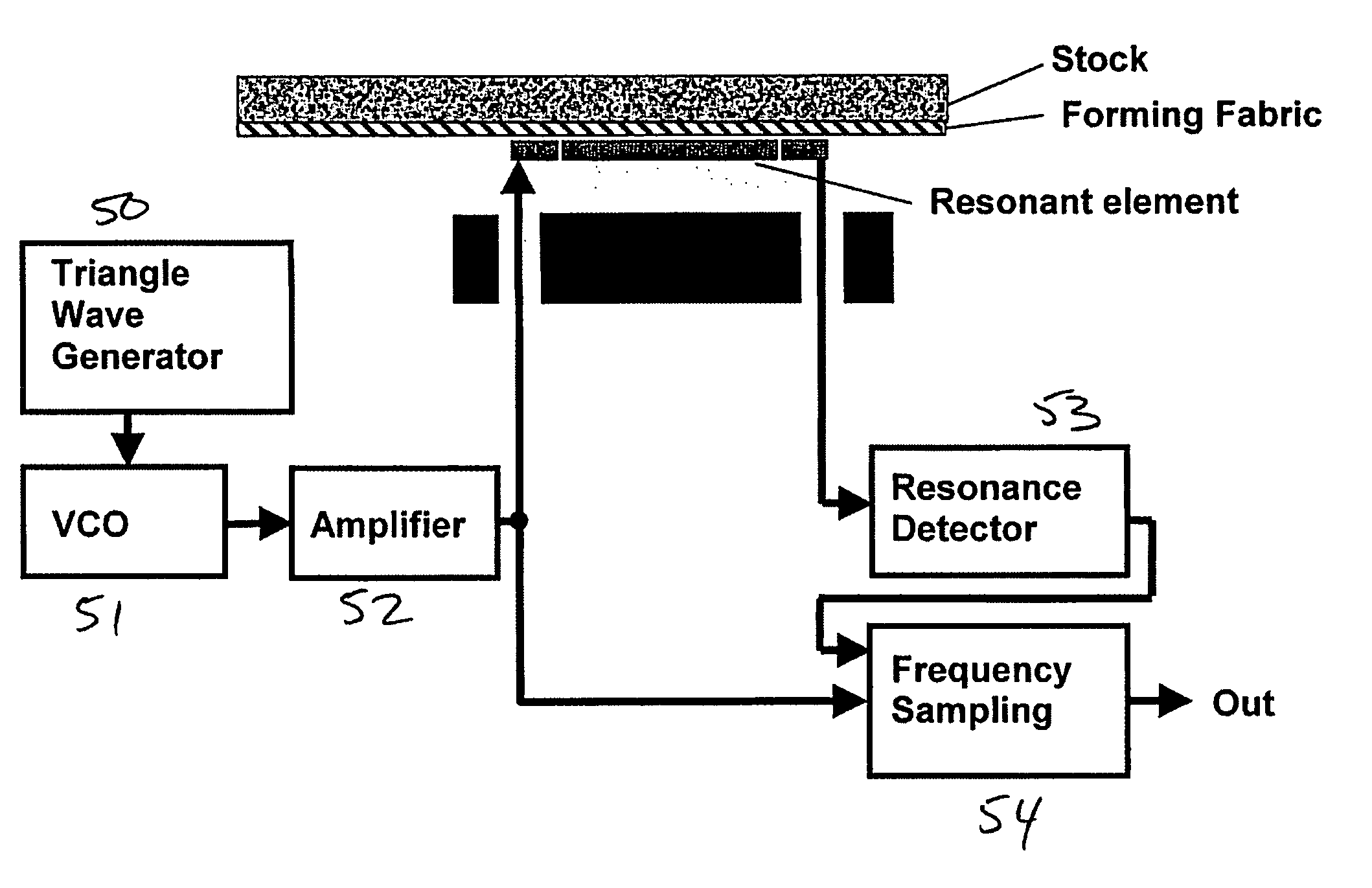
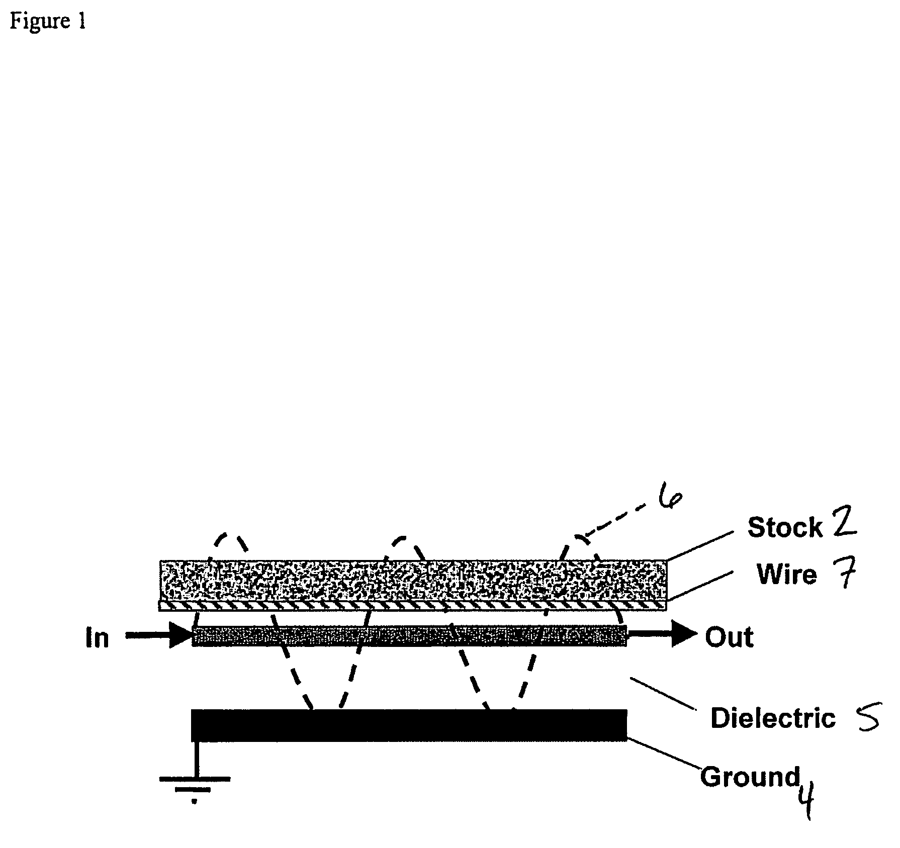
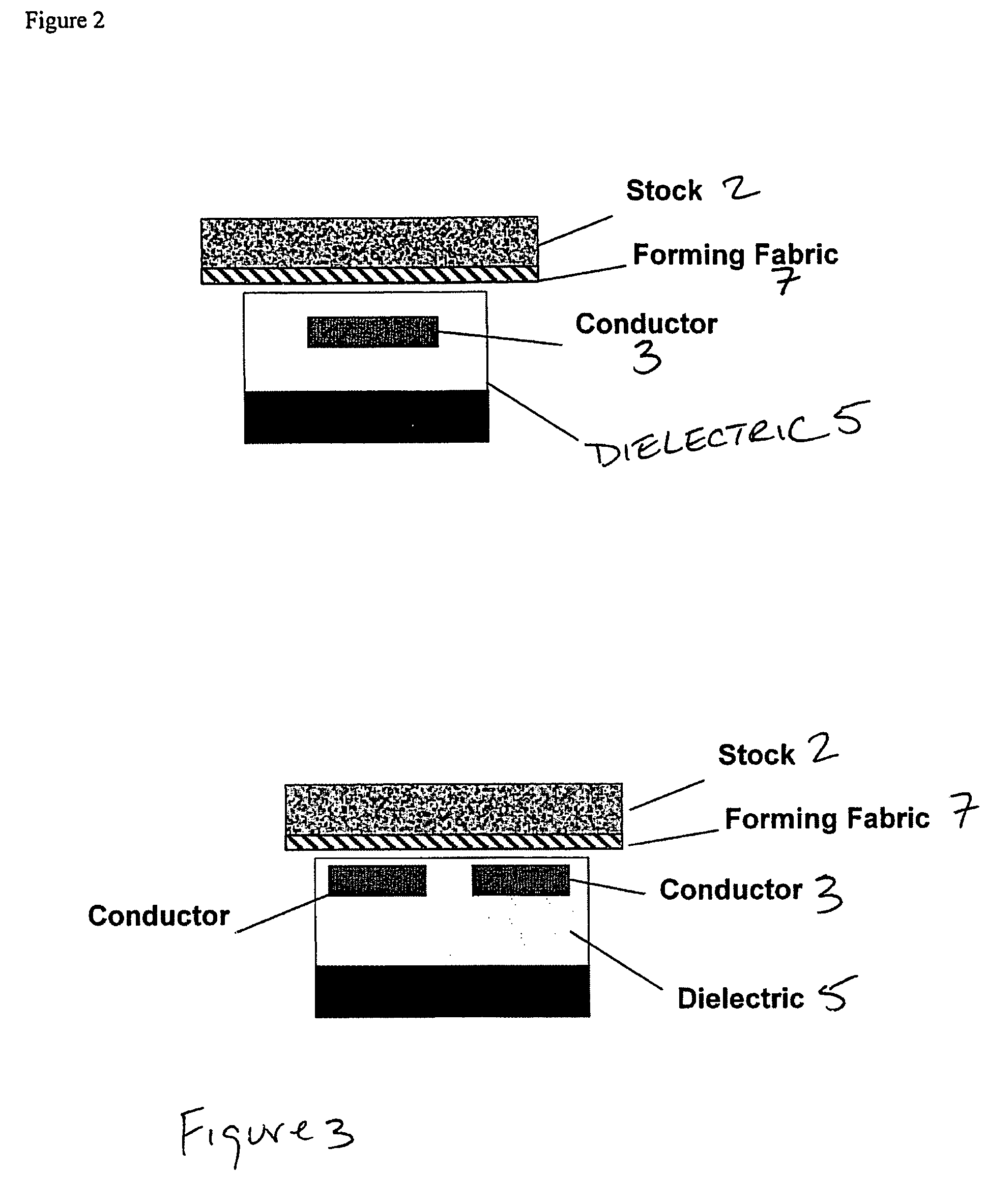
The present invention provides a small and powerful microwave sensor that can be installed in a ceramic foil to measure the water weight in a paper machine forming section. The sensor creates a microwave field that is partially in the material to be measured, and the measurement is based on the wave propagation velocity influenced by the dielectric constant of the materials around the transmission lines or in the space between the transmitter and receiver antennae. The sensor is cost-effective and can be used in double wire forming sections or to produce non-scanning measurement profiles. It can also be used to determine the drainage profile and can be installed inside a ceramic foil to measure water weight simultaneously at various cross-machine direction positions. The sensor is formed as a stripline or slotline microwave transmission line or a planar resonator in the ceramic foil. The operating frequency is chosen to be below the relaxation frequency of water to allow for the use of widely available integrated circuits. The sensor can be used in cross-machine and machine direction arrays to determine the drainage profile.

Problems solved by technology

However, these device are limited in that the water weight is indirectly determined, i.e., calculated from the measurement of another parameter.
Thus, this device provides essentially a “layer-thickness-measurement,” however, it cannot be used after the dry line.
However, this device is disadvantageous in that measurement noise is high and that the measurement requires the use of radioactive material.
However, the size of these devices do not match the space requirements for paper making installations.
While the described method uses a sensor that measures the moisture content (water weight) through the sheet supporting fabric, none of the commercially available microwave sensors are suited for this application, i.e., as noted above, the sensors such as the ScanPro do not match the space requirements.
Thus, these sensors are not suited for measuring water through the forming fabric.
However, like the other noted devices, the resonant cavity is too large for satisfactory use in the forming section.

Method used


Image

  • Microwave water weight sensor and process
  • Microwave water weight sensor and process
  • Microwave water weight sensor and process

Examples


Embodiment Construction

[0033]The particulars shown herein are by way of example and for purposes of illustrative discussion of the embodiments of the present invention only and are presented in the cause of providing what is believed to be the most useful and readily understood description of the principles and conceptual aspects of the present invention. In this regard, no attempt is made to show structural details of the present invention in more detail than is necessary for the fundamental understanding of the present invention, the description taken with the drawings making apparent to those skilled in the art how the several forms of the present invention may be embodied in practice.

[0034]FIG. 1 illustrates a sensor 1 in accordance with the features of the present invention. In particular, sensor 1 can be positioned adjacent the sheet or web 2 supported on a forming fabric (plastic wire) 7 in a sheet forming section, where sheet 2 is almost all water. Sensor 1, which is a microwave element, includes ...


PUM


Abstract

Sensor and process for measuring mass of water on a sheet forming fabric. The sensor includes a microwave element positionable to couple an electromagnetic field into a stock layer to be measured, and a microwave signal generator coupled to the microwave element to generate, in the microwave element, a microwave signal having a frequency lower than a relaxation frequency of water. The instant abstract is neither intended to define the invention disclosed in this specification nor intended to limit the scope of the invention in any way.

Description

FIELD OF THE INVENTION [0001]The present invention is directed to a sensor and process for measuring water weight in the forming section of a paper making machine using microwaves.DISCUSSION OF BACKGROUND INFORMATION [0002]Various devices are known for determining the water weight in the forming section. However, these device are limited in that the water weight is indirectly determined, i.e., calculated from the measurement of another parameter. One such device (Honeywell SpectraFoil) calculates the water weight based upon a measurement of the conductance of the stock layer on the former. This device measures the electric current through the stock and is sensitive to chemical changes in the stock.[0003]Another method described in U.S. Pat. Nos. 3,442,756 and 4,789,431 provides an ultrasonic measurement of the stock layer thickness by measuring reflectance of the ultrasonic sound from the top and bottom surface of the stock. Thus, this device provides essentially a “layer-thickness-...

Claims


Application Information

Patent Timeline
Patent Type & Authority Patents(United States)
IPC IPC(8): G01R27/32G01G9/00
CPCD21G9/0027G01N22/04G01N33/367
Inventor TYPPÖ, PEKKAMÜNCH, RUDOLFISCHDONAT, THOMASKAUFMANN, OLIVER
Owner VOITH PATENT GMBH
Learn More