
Ink jet printer head and method for fabricating the same

a printer head and printer technology, applied in the direction of printing, piezoelectric/electrostrictive transducers, transducer types, etc., can solve the problems of poor energy efficiency and poor mass-productivity of the technique disclosed in the same, and achieve the effect of improving mass-productivity

Inactive Publication Date: 2006-09-19
TOSHIBA TEC KK
View PDF7 Cites 2 Cited by
  • Summary
  • Abstract
  • Description
  • Claims
  • Application Information

AI Technical Summary

Benefits of technology

The present invention provides a method for fabricating an ink jet printer head that allows multiple ink jet printer heads to be obtained from a single substrate, improving mass-productivity. Additionally, the invention aims to prevent the formation of air bubbles in adhesive layers, prevent short-circuit of electrodes with adjacent elements, and improve print quality by preventing variations in deformation of piezoelectric members. The invention also aims to improve energy efficiency and facilitate the formation of electrodes of a required film thickness in fine grooves. The invention provides an ink jet printer head comprising a head substrate formed by cutting a pre-polarized piezoelectric member into a desired width and embedding it into a recess of a base member, forming a plurality of desired grooves in the piezoelectric body-embedded side of the substrate, and forming an electrically conductive film on inner walls of at least some of the grooves. The invention also provides an ink jet printer head comprising a head substrate formed by cutting two pre-polarized piezoelectric members into a desired width and embedding them into a recess of a base member, forming a plurality of desired grooves in the piezoelectric body-embedded side of the substrate, and forming an electrically conductive film on inner walls of at least some of the grooves.

Problems solved by technology

For these reasons, even a portion not concerned in ink jet have a large capacitance, thus giving rise to the problem that the energy efficiency is poor.
Hei 7-101056 there is disclosed nothing disclosed about means for obtaining a large number of ink jet printer heads from a single substrate and thus the technique disclosed therein is poor in mass-productivity.
Since electrodes are formed within grooves, if air bubbles or the like are formed in adhesive layers, the electrodes may be short-circuited with adjacent elements, or conversely the electrodes may not be connected well on the adhesive layers, which is apt to cause an accident of open circuit.

Method used


Image

  • Ink jet printer head and method for fabricating the same
  • Ink jet printer head and method for fabricating the same
  • Ink jet printer head and method for fabricating the same

Examples


Embodiment Construction

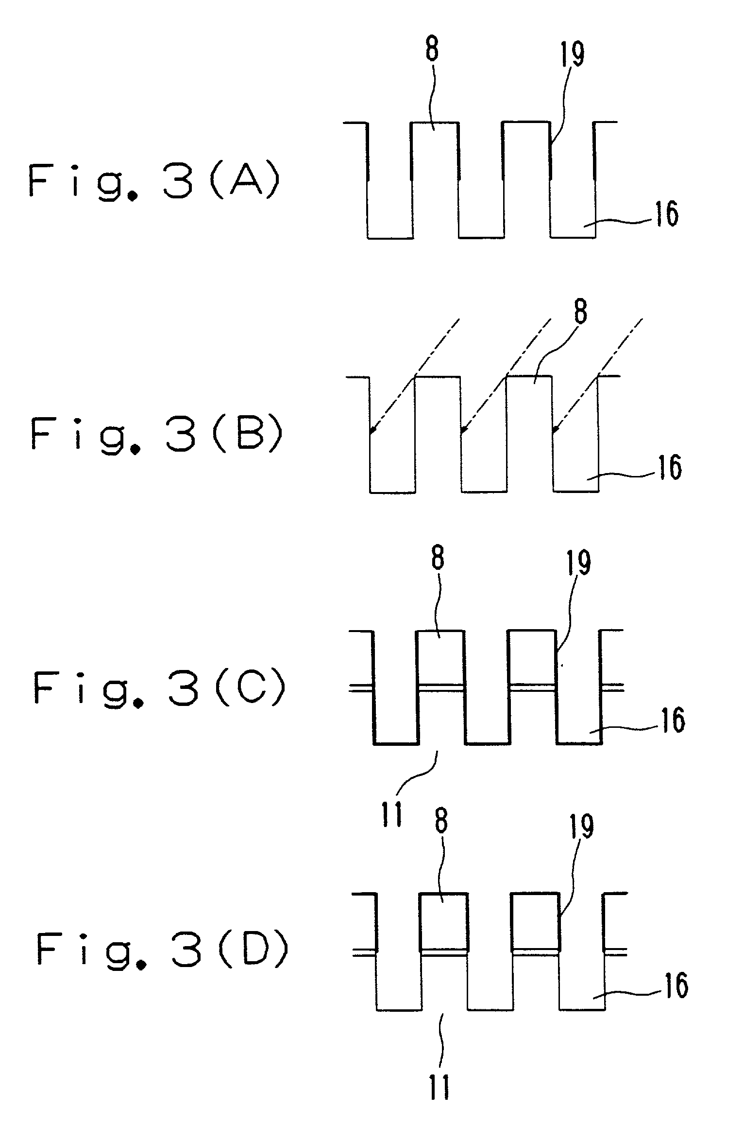
[0057]The first embodiment of the present invention will now be described with reference to FIGS. 2 to 11. As shown in FIG. 2, an ink jet printer head 7 embodying the present invention has such a structure as shown in FIG. 2. According to the illustrated structure, a piezoelectric member 8 using a piezoelectric material such as PZT (lead zirco-titanate) is cut into predetermined shape and size to form a piezoelectric body 25, the piezoelectric body 25 is combined with a base member 11 formed using a material smaller in dielectric constant than the piezoelectric member 8 to constitute a laminate substrate 12, the laminate substrate 12 and a top plate 13 are bonded or joined together to form a substrate-top plate composite 14, and a nozzle plate 15 having a thickness of about 10 to 100 μm is integrally bonded to the substrate-top plate composite 14.

[0058]The piezoelectric member 8 formed of PZT is polarized in the plate thickness direction. The laminate substrate 12 with the piezoelec...


PUM

PropertyMeasurementUnit
thicknessaaaaaaaaaa
sizeaaaaaaaaaa
sizeaaaaaaaaaa

Abstract

A plurality of ink jet printer heads can be obtained from a single substrate through the following steps: a piezoelectric body forming step of cutting a piezoelectric member into a desired width to form a piezoelectirc body, a fitting recess forming step of forming a recess for fitting therein of the piezoelectric body in a base member, a substrate forming step of embedding the piezoelectric body into the recess to form a substrate, a grooving step of forming a plurality of desired grooves in parallel in the substrate, a head substrate forming step of forming an electrically conductive film on inner walls of the grooves to form a head substrate, an electroconductive pattern forming step of making connection to the electrically conductive film for the application of voltage thereto, a top plate joining step of joining a top plate to the head substrate to form a head substrate-top plate composite, a head forming step of cutting the head substrate-top plate composite at a desired position to form a head, and a nozzle plate joining step of joining a nozzle plate to a cut side having groove openings of the head.

Description

BACKGROUND OF THE INVENTION[0001]1. Field of the Invention[0002]The present invention relates to an ink jet printer head to be used, for example, in a printer, a copying machine, or a facsimile device, as well as a method for fabricating the same. Particularly, the invention is concerned with an ink jet printer head capable of being obtained from a single substrate, as well as a method for fabricating the same.[0003]2. Description of the Prior Art[0004]Heretofore, various types of ink jet printer heads utilizing a shear mode of a piezoelectric material have been proposed, including the one disclosed in Japanese Unexamined Patent Publication No. Sho 63-247051. In many of them, however, as pointed out in Japanese Unexamined Patent Publication No. Hei 7-101056, fine grooves serving as pressure chambers are formed by means of a diamond blade and the piezoelectric material typified by PZT (lead zirco-titanate) is ferroelectric. For these reasons, even a portion not concerned in ink jet h...

Claims


Application Information

Patent Timeline
Patent Type & Authority Patents(United States)
IPC IPC(8): B41J2/045H04R17/00B41J2/055B41J2/16
CPCB41J2/1609B41J2/1623B41J2/1632B41J2/1643Y10T29/49798Y10T29/42Y10T29/49401
Inventor SHIMOSATO, MASASHIKOIZUMI, SHINJIKIKUCHI, TAKASHI
Owner TOSHIBA TEC KK
Learn More