Permanent magnet rotor

a permanent magnet and rotor technology, applied in the direction of magnetic circuit rotating parts, dynamo-electric machines, magnetic circuit shape/form/construction, etc., can solve the problems of difficult pressing the rubber into the slot, damage to the magnet structure of patent document 1, etc., to prevent the vibration of the magnet, simple shape, and low cost

Inactive Publication Date: 2015-10-20
MITSUBISHI ELECTRIC CORP
View PDF19 Cites 0 Cited by
  • Summary
  • Abstract
  • Description
  • Claims
  • Application Information

AI Technical Summary

Benefits of technology

[0007]The invention was devised to solve the problems discussed above and has an object to provide a permanent magnet rotor capable of not only preventing damage on a permanent magnet by reducing resonance even when the magnet resonates under a vibration condition, but also enhancing mass-productivity by making a process involving magnet fixation simpler.
[0009]When configured in this manner, it becomes possible to attenuate vibrations of the magnet. Hence, damage on the magnet caused by vibrations can be prevented. Also, because the parts necessary for fixation are of a simple shape, an assembling process becomes simple, too. Consequently, the permanent magnet rotor can be mass-produced at a low cost. The foregoing and other object, features, aspects, and advantages of the present invention will become more apparent from the following detailed description of the present invention when taken conjunction with the accompanying drawings.

Problems solved by technology

The structure of Patent Document 1, however, may damage the magnet because the metal split pin hits against the magnet when the magnet and the split pin vibrate due to resonance.
Strong friction of the rubber, however, makes it difficult to press-fit the rubber into the slot.
This alternative therefore requires an arrangement to insert the rubber while letting the rubber undergo elastic deformation by applying an external force to the rubber and has a problem that the process becomes complex.

Method used


Image

  • Permanent magnet rotor
  • Permanent magnet rotor
  • Permanent magnet rotor

Examples


first embodiment

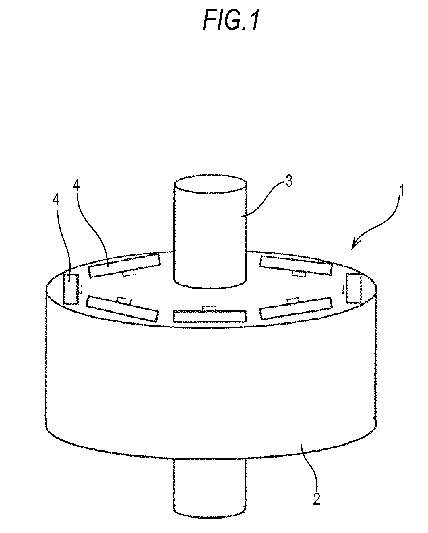
[0018]FIG. 1 is a perspective view of a permanent magnet rotor 1 of the invention. The rotor 1 is formed by fixedly fitting a rotor core 2 to a rotation shaft 3. The rotor core 2 is formed by laminating plates of a magnetic material, such as silicon steel plates, punched out by a mold. The rotor core 2 is provided with a plurality of permanent magnet embedment slots (hereinafter, referred to simply as the magnet embedment slots or slots) 4 to embed permanent magnets. The magnet embedment slots 4 are provided parallel to the shaft 3 at equally spaced positions closer to an outer periphery.

[0019]FIG. 2 is a detailed view on a periphery of the magnet embedment slot 4. The magnet embedment slot 4 is formed of a magnet storing portion 4a in a rectangular shape comforting to a shape of a magnet and a buffer and other members storing portion 4b continuing to the magnet storing portion 4a at substantially the center of a long side of the magnet storing portion 4a. The magnet storing portion...

second embodiment

[0024]FIG. 4 through FIG. 6D show a second embodiment of the invention and members in common with FIG. 1 through FIG. 3C are labeled with the same reference numerals. A difference of a permanent magnet rotor of the second embodiment from the counterpart of the first embodiment above is the pushing member. As is shown in FIG. 4, a magnet embedment slot 4 in the permanent magnet rotor of the second embodiment is formed of a magnet storing portion 4a in a rectangular shape conforming to a shape of a permanent magnet 7 and a rectangular buffer and other members storing portion 4c continuing to the magnet storing portion 4a substantially at the center of a long side of the magnet storing portion 4a. The magnet storing portion 4a and the buffer and other members storing portion 4c are formed simultaneously by punching. The buffer and other members storing portion 4c is of a rectangular shape herein. It should be appreciated, however, that the buffer and other members storing portion 4c ma...

third embodiment

[0029]FIG. 7 and FIGS. 8A through 8C show a periphery of a magnet embedment slot 4 in a permanent magnet rotor of a third embodiment. In the first and second embodiments above, the buffer member 8 and the pushing member 9 or 9a are separate parts, and when assembled, the pushing member 9 or 9a is inserted into the buffer and other members storing portion 4c after the buffer member 8 is inserted therein. On the contrary, the third embodiment uses a buffer and pushing member 11 prepared by making a plate-shaped buffer member 8 and a pushing member 9, which is a resin or metal split pin, into one piece with an adhesive 10. The rest of the configuration is the same as the configuration of the first or second embodiment above, and a description is omitted by labeling the common components with the same reference numerals. Referring to FIG. 7, the buffer and the pushing member 11 is formed of the pushing member 9 in the shape of a split pin and the buffer member 8. It should be appreciate...


PUM


Abstract

A permanent magnet rotor has a rotor core positioned about a rotation shaft. The permanent magnet rotor also has permanent magnet embedment slots located at equally spaced positions from the rotation shaft, with permanent magnets inserted into each of the respective permanent magnet embedment slots. The permanent magnet embedment slots each have both a magnet storing portion, and a buffer and other members storing portion which extends to the magnet storing portion. Once a permanent magnet is stored inside the magnet storing portion, a buffer member, and a pushing member are used to secure the permanent magnet inside the rotor core.

Description

BACKGROUND OF THE INVENTION[0001]1. Field of the Invention[0002]The present invention relates to a permanent magnet rotor (hereinafter, referred to also simply as the rotor) formed by inserting a permanent magnet (hereinafter, referred to also simply as the magnet) into a rotor of an electric motor.[0003]2. Background Art[0004]To obtain a permanent magnet rotor by inserting a permanent magnet into an internal slot of an electric motor rotor and fixing the magnet therein, an adhesive, such as epoxy resin, may be applied between the internal slot and the magnet and cured to fix the magnet. However, this method requires a thermal curing process to cure the adhesive and admits of improvement in terms of mass-production. As an alternative, there is proposed a method that eliminates the need of a complex process by providing a groove in an inner peripheral portion of the internal slot and inserting a magnet fixing metal split pin into the groove after a permanent magnet is inserted into t...

Claims


Application Information

Patent Timeline
Patent Type & Authority Patents(United States)
IPC IPC(8): H02K1/28H02K1/27
CPCH02K1/276H02K1/28
Inventor NAKAMURA, MASASHIYOKOTA, HIROHISAOKAMOTO, SHOGOINOUE, MASAYA
Owner MITSUBISHI ELECTRIC CORP
Why Eureka
Try Eureka