
Electrochromic device

a technology of electrochromic devices and electrodes, applied in the direction of luminescent compositions, instruments, photosensitive materials, etc., can solve the problems of not being able to operate in transmitted light, not being able to allow a large number of switching cycles, and devices that are not particularly stabl

Inactive Publication Date: 2006-09-12
BAYER AG
View PDF8 Cites 20 Cited by
  • Summary
  • Abstract
  • Description
  • Claims
  • Application Information

AI Technical Summary

Problems solved by technology

These devices are not self-erasing, i.e. the image produced remains after the current has been switched off and can only be erased again by reversing the voltage.
Such devices are not particularly stable and do not allow a large number of switching cycles.
In addition, such cells constructed using tungsten oxide / palladium hydride in particular cannot be operated in transmitted light, but only reflectively, owing to light scattering at these electrochromic layers.
When the voltage is switched off, the ground state re-forms in the case of both substances, resulting in disappearance or fading of the colour.
However, complex mixtures of this type are difficult to balance, especially when the electrochromic device is to be operated at different voltages and the colour is to be independent from the voltage.
Furthermore, the dipyridinium salt and dihydrophenazine derivatives disclosed in WO 98 / 44384 are not always readily obtainable.

Method used


Image

  • Electrochromic device
  • Electrochromic device
  • Electrochromic device

Examples


example 1

[0279]9.6 g of 3-phenyl-1-bromopropane were added dropwise over the course of 45 min to 15.0 g of 4,4′-bipyridyl in 90 ml of toluene at 70° C. The mixture was stirred for 24 h at reflux temperature, cooled down and the solid was filtered off with suction. The solid was stirred in 90 ml of toluene for 4 h at reflux temperature, cooled down, filtered off with suction and washed with toluene. Drying in vacuo gave 14.3 g (85% of theory) 4-(4-pyridyl)-1-(3-phenylpropyl)pyridinium bromide.

[0280]2.5 g of the above product were stirred with 0.7 g of 1,3-dibromopropane in 35 ml of butyrolactone with the addition of 0.1 g of tetrabutylammonium iodide at 70° C. for 48 h. The mixture was cooled down, and the solid was filtered off with suction, washed with a little butyrolactone and toluene and dried in vacuo. 3.0 g (94% of theory) of the electrochromic substance of the formula (CCCIa) were obtained as a beige powder.

[0281]

[0282]1H NMR ([D6]-DMSO): δ=2.36 (quint.), 2.71 (t), 2.83 (quint.), 4.78...

example 2

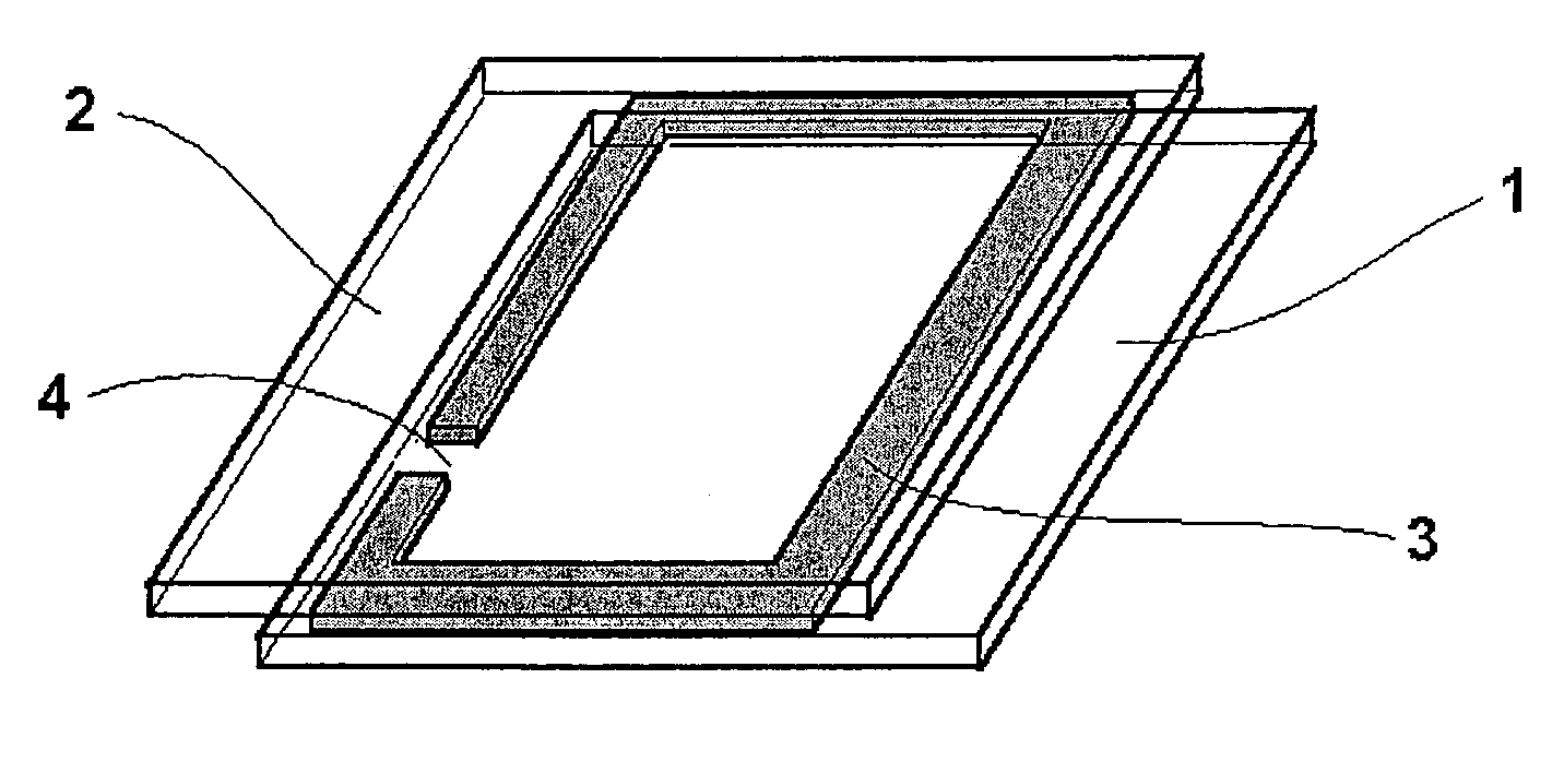
[0288]A cell was constructed as shown in FIG. 1. To this end, two glass plates 1 and 2 coated on one surface with ITO were used.

[0289]A mixture of 97% of photocuring DELO-Katiobond® 4594 epoxy adhesive (DELO Industrieklebstoffe, Landsberg) and 3% of glass beads with a diameter of 200 μm were applied in a ring shape 3 to the ITO-coated side of glass plate 1 in such a way that a 2 mm wide opening 4 was left. Glass plate 2 was then placed on the adhesive bead in such a way that the ITO layers of the two plates 1 and 2 were facing one another and a geometry as shown in FIG. 1 was formed. The adhesive was cured by exposure for 10 minutes to daylight in the vicinity of a window and then for 20 minutes at 105° C. without exposure to light.

[0290]A dish was filled under a nitrogen atmosphere with a solution which was 0.02 molar with respect to the electrochromic compound of the formula

[0291]

0.0025 molar with respect to the electrochromic compound of the formula

[0292]

and 0.005 molar with resp...

example 3

[0298]A cell was constructed as described in Example 2 except that the electrochromic compound of the formula (CCCII) was used in a concentration of 0.01 mol.

[0299]Application of a voltage of 1.2 V to the two plates 1 and 2 caused the cell rapidly to turn black. Switching off the voltage and short-circuiting the contacts caused the colour rapidly to disappear again. 100 000 switching cycles of this type were conducted without any change in the switching behaviour.

[0300]In the coloured state, the cell displayed absorption maxima at 399 nm, 466 nm, 550 nm, 606 nm, 665 nm and 738 nm having absorbencies of 5.36, 2.06, 1.78, 1.82, 1.25 and 0.81, respectively.


PUM


Abstract

An electrochromic device comprising a pair of glass, plastic plates or plastic films At least one plate or film, is provided with an electrically conductive coating. At least one plate or film and its conductive coating are transparent and the other may be mirrored. The plates or films are joined together and form a volume filled with an electrochromic medium which comprises at least one reducible electrochromic substance OX2 and at least one oxidizable electrochromic substance RED1. The OX2 corresponds to the formulain which R201 and R202, each are alkyl, cycloalkyl, alkenyl, aralkyl, aryl, −[C(PQ)]− or a bivalent bridge B, Z201 is a bivalent radical of the formulae CR210R211, O, C═O or o-phenylene, R210 and R211, each are hydrogen, methyl or ethyl, or CR210R211 is C3- to C7-cycloalkane-1,1-diyl. The rings C, D, E and F, each may be substituted by up to 4 alkyl and / or alkoxy radicals, or respectively, may be linked via a —(CH2)4— or —CH═CH—CH═CH— bridge. P and Q, each are —CN or —COO-alkyl. X— is an anion.

Description

BACKGROUND OF THE INVENTION[0001](1) Field of the Invention[0002]The present invention relates to an electrochromic device, and to electrochromic substances.[0003]Electrochromic devices are already known, for example from D. Theis in Ullmann's Encyclopaedia of Industrial Chemistry, vol. A 8, p. 622, Verlag Chemie 1987 and WO-A 94 / 23333. A distinction is made between two basic types:[0004](2) Description of Related Art[0005]Type 1: full-area electrochromic devices;[0006]Type 2: electrochromic display devices having structured electrodes.[0007]Type 1 is used, for example, in electrically darkenable window panes or electrically dimmable automobile mirrors. Such devices are disclosed, for example, in U.S. Pat. No. 4,902,108.[0008]Type 2 is used in segment and matrix displays. Such display devices are proposed, for example, in DE-A 196 31 728. Devices of this type can be observed transmissively or, in the case of reflection, reflectively.[0009]WO-A 94 / 23333 compares electrochromic materi...

Claims


Application Information

Patent Timeline
IPC IPC(8): G02F1/153G03G5/00C09K9/02G02F1/1503
CPCG02F1/1521C09K9/02G02F1/1503C09K11/06
Inventor BERNETH, HORSTNEIGL, RALFSHELEPIN, IGORGAVRILOV, VLADIMIR
Owner BAYER AG
Learn More