PET scanner

a technology scanner, which is applied in the field of positron emission tomography (pet) camera or scanner, can solve the problems of increasing the cost, reducing the spatial resolution at the edge and geometric limitation of the spatial resolution at the end of the field of view of the pet scanner

Inactive Publication Date: 2006-09-05
EUROPEAN ORGANIZATION FOR NUCLEAR RESEARCH
View PDF31 Cites 19 Cited by
  • Summary
  • Abstract
  • Description
  • Claims
  • Application Information

AI Technical Summary

Problems solved by technology

This, however, increases the cost.
In addition to limitations on the spatial resolution of known PET scanners, there is also a geometrical limitation on the spatial resolution at the end of a PET scanner field of view.
In practice, however, the stopping power being limited by the density of the material the detector needs to have a certain length, typically one to three centimetres which reduces the spatial resolution at the edge of the field of view.
This is a disadvantage.
Unfortunately, the photoelectric absorption coefficient of GSO is much less than that of LSO.
This means that the stopping power of the GSO is limited, which introduces a degree of uncertainty into the determination of the hit layer.
A disadvantage of this particular device is, however, that the difference in decay time constants of “fast” and “slow” LSO is only about 10% (4–5 nanoseconds at mean value of 40 ns).
Hence, there can be difficulty in determining the hit layer with any certainty.

Method used


Image

  • PET scanner
  • PET scanner
  • PET scanner

Examples


Embodiment Construction

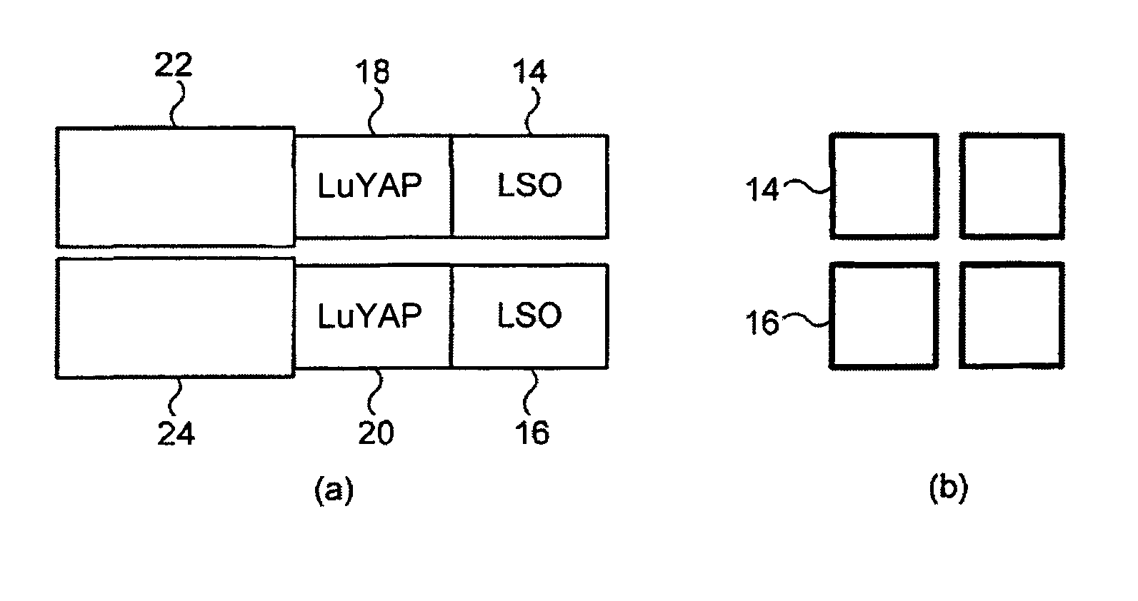
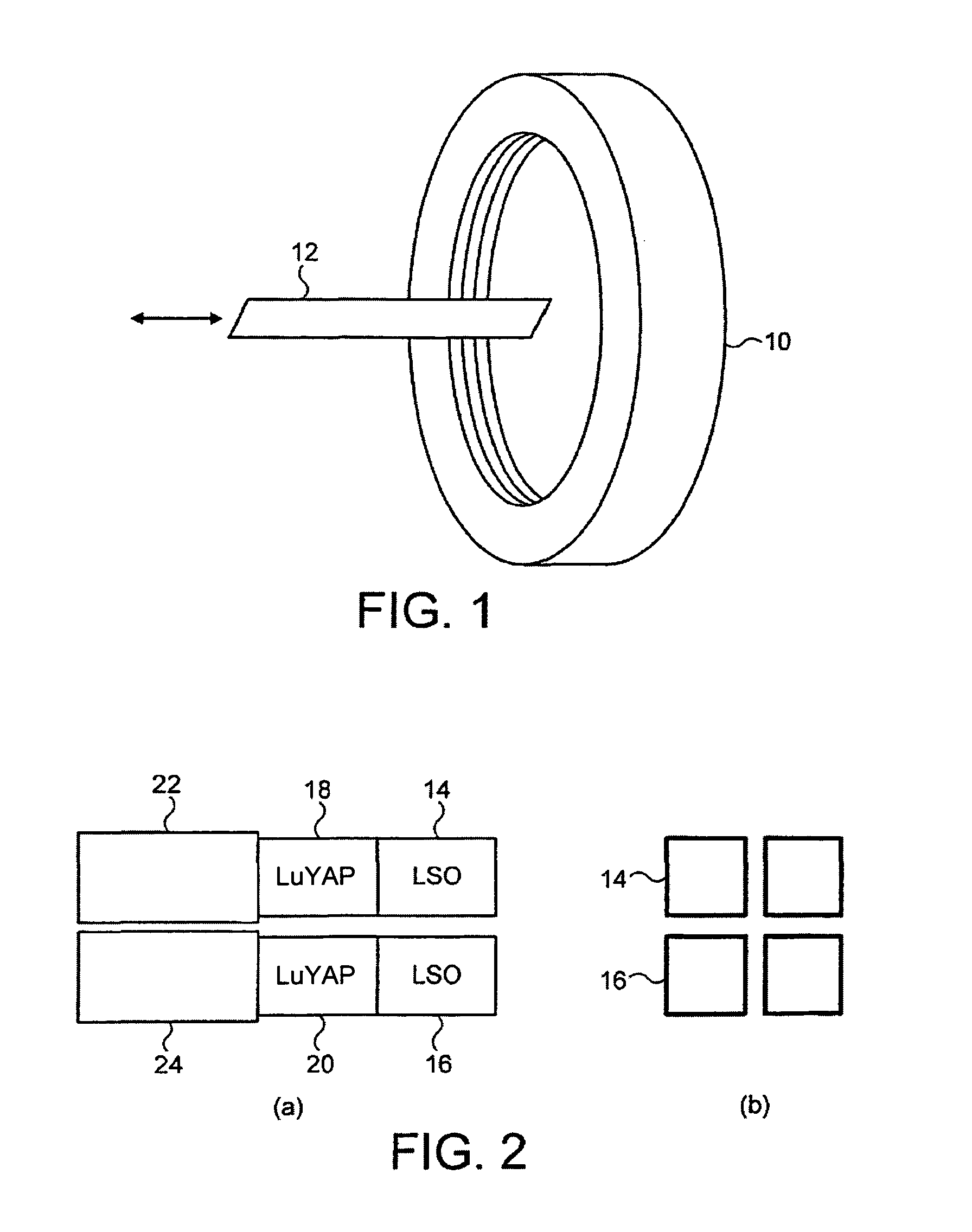
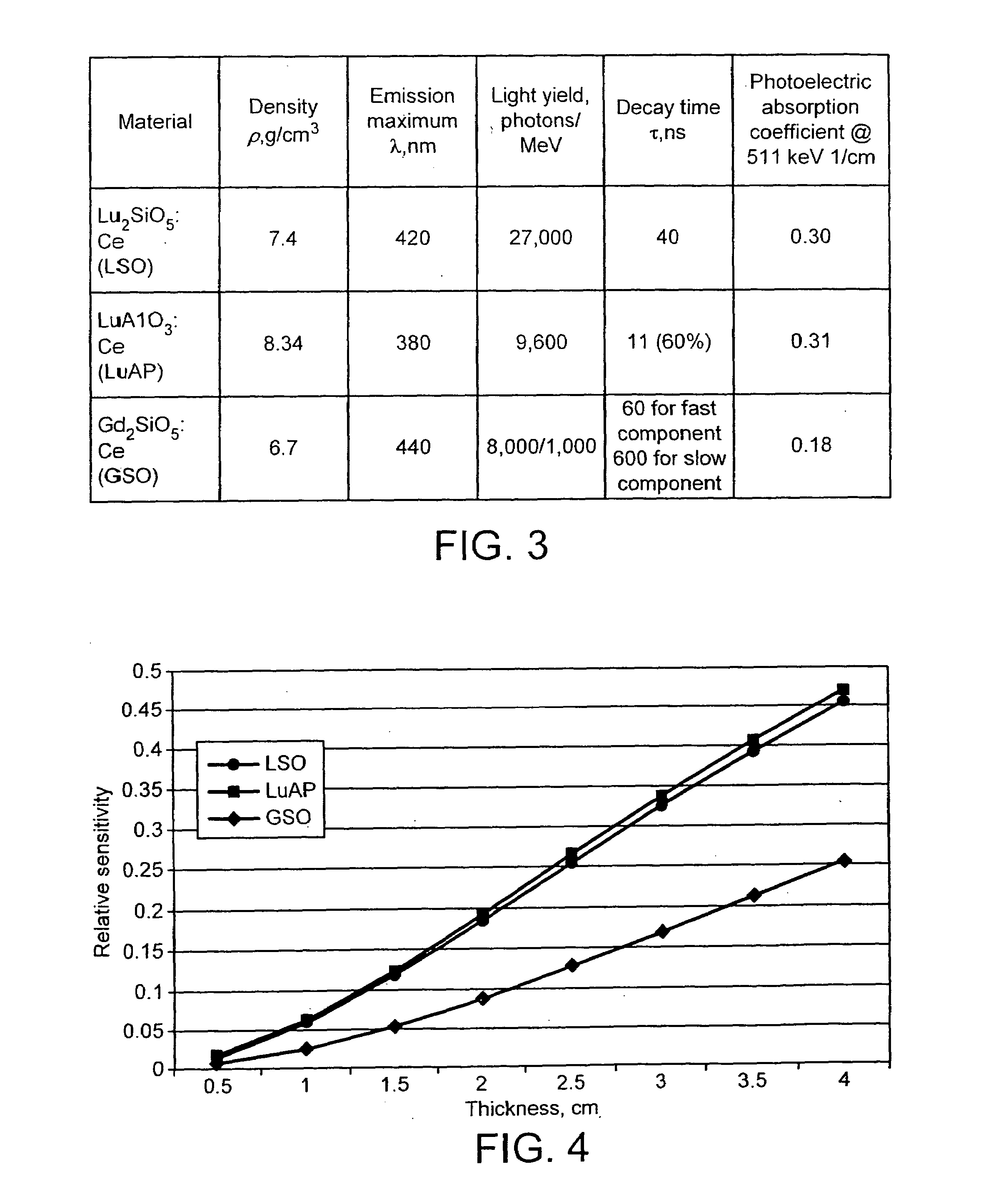
[0040]The PET in which the invention is embodied uses scintillators that comprise lutetium based crystals. In particular, the scintillator in which the invention is embodied uses lutetium-yttrium-aluminate-perovskite, with the proportions of Lu and Y defined by LuxY1−xAP (where 0.5≦x≦0.995). This material has many properties that make it useful as a scintillator; hereinafter it is referred to as Lu YAP.

[0041]FIGS. 2(a) and (b) show two scintillators for a PET scanner, each of which comprises an inner layer of LSO 14,16 and a layer of LuYAP 18,20. Each layer of LSO and LuAP is preferably less than 20 mm thick. Adjacent each LuYAP layer 18, 20 and optically coupled thereto is a photodetector 22,24 for detecting light emitted either from the LSO 14,16 or the LuAP 18,20. The photodetectors 22,24 can be of any suitable type, but typically include photo-multipliers or avalanche photodiodes. Signals from the photodetectors 22,24 are processed using read-out electronics (not shown). In prac...


PUM


Abstract

A positron emission camera comprising a plurality of scintillators, wherein the scintillators include LuAlO3:Ce (LuxY1−xAP where 0.5≦x≦0.995) based crystals (18,20). In particular, the scintillation crystals (18,20) are LuxY1−xAP where 0.5≦x≦0.995.

Description

CROSS-REFERENCE TO RELATED APPLICATION[0001]This application is a Continuation-In-Part of U.S. application Ser. No. 09 / 892,201, filed Jun. 26, 2001 now abandoned, which is incorporated herein by reference.FIELD OF THE INVENTION[0002]The present invention relates to a positron emission tomography (PET) camera or scanner, and to a scintillator for such a camera or scanner.BACKGROUND OF THE INVENTION[0003]PET scanners are well known in the field of medical physics. These scanners produce images of the body by detecting radiation emitted from radioactive substances injected into the body. Each scanner is made up of radiation detectors, typically called scintillators, which are arranged in a ring configuration around a movable patient table. A typical arrangement with a detector ring 10 and a patient table 12 is shown in FIG. 1. Each scintillator comprises a crystal and has an associated partner located opposite it on the ring. Many known cameras use Bi4Ge3O12 (BGO) as a scintillation de...

Claims


Application Information

Patent Timeline
Patent Type & Authority Patents(United States)
IPC IPC(8): G01T1/20G01T1/164
CPCG01T1/202G01T1/2985A61B6/037G01T1/2008
Inventor LECOQ, PAUL
Owner EUROPEAN ORGANIZATION FOR NUCLEAR RESEARCH
Why Eureka
Try Eureka