
Optical receiver with high dynamic range

a receiver and high-distribution technology, applied in the field of optical receivers, can solve the problems of attenuation of signals, power level variations, power levels that may also vary, etc., and achieve the effect of increasing the responsivity of the photo-detector and increasing the effective thickness of the absorption layer

Inactive Publication Date: 2006-06-27
LUMENTUM OPERATIONS LLC
View PDF19 Cites 24 Cited by
  • Summary
  • Abstract
  • Description
  • Claims
  • Application Information

AI Technical Summary

Benefits of technology

This solution enhances the dynamic range of the optical receiver by two orders of magnitude and improves sensitivity by reducing insertion loss and the number of optical interfaces, while allowing for high-yield, high-volume fabrication and reduced complexity and cost.

Problems solved by technology

Reconfigurable networks that employ active switching, add-drop multiplexing, and wavelength routing cause power level variations.
Power levels may also vary as a result of component degradation due to aging or reduction in fiber coupling efficiency.
Rotation of the mirror changes coupling to the output waveguide by lateral displacement (miscoupling) of the light distribution relative to the waveguide which thus causes attenuation of the signal.
Combining the aforementioned VOAs with a receiver requires coupling of the output fiber to the receiver, thus causing additional insertion loss and, as a consequence of that, degradation in the sensitivity of the combined solution.
Integration of that type of VOA with receiver in a single package therefore requires accurate alignment of the active area of the detector to the output beam of VOA, thereby increasing complexity and cost of the packaged solution.
However, reducing the absorption layer thickness will also increase the capacitance of the photodiode which tends to decrease bandwidth.
The capacitance can be independently reduced by making the device area smaller, but reduction in photosensitive area makes the efficient coupling of light difficult thus reducing the coupling efficiency and increasing the sensitivity to optical misalignment.
The fundamental limitation on the coupling efficiency is due to diffraction when free-space micro-optical components are used.
In all cases, the reduction in absorption layer thickness lowers the intrinsic quantum efficiency of the detector for surface-normal illumination.
These mode transformers introduce additional sources of losses to the device and are difficult to fabricate.
There are several disadvantages in using these existing techniques.
In case of the etched TIR mirror, the etching weakens the (already) fragile PD chip.
In addition, the mirror surface should be positioned accurately relative to photosensitive area of the PD, which may be difficult to accomplish.
The above coupling schemes also suffer from poor coupling efficiency due to beam divergence caused by diffraction.

Method used


Image

  • Optical receiver with high dynamic range
  • Optical receiver with high dynamic range
  • Optical receiver with high dynamic range

Examples


Embodiment Construction

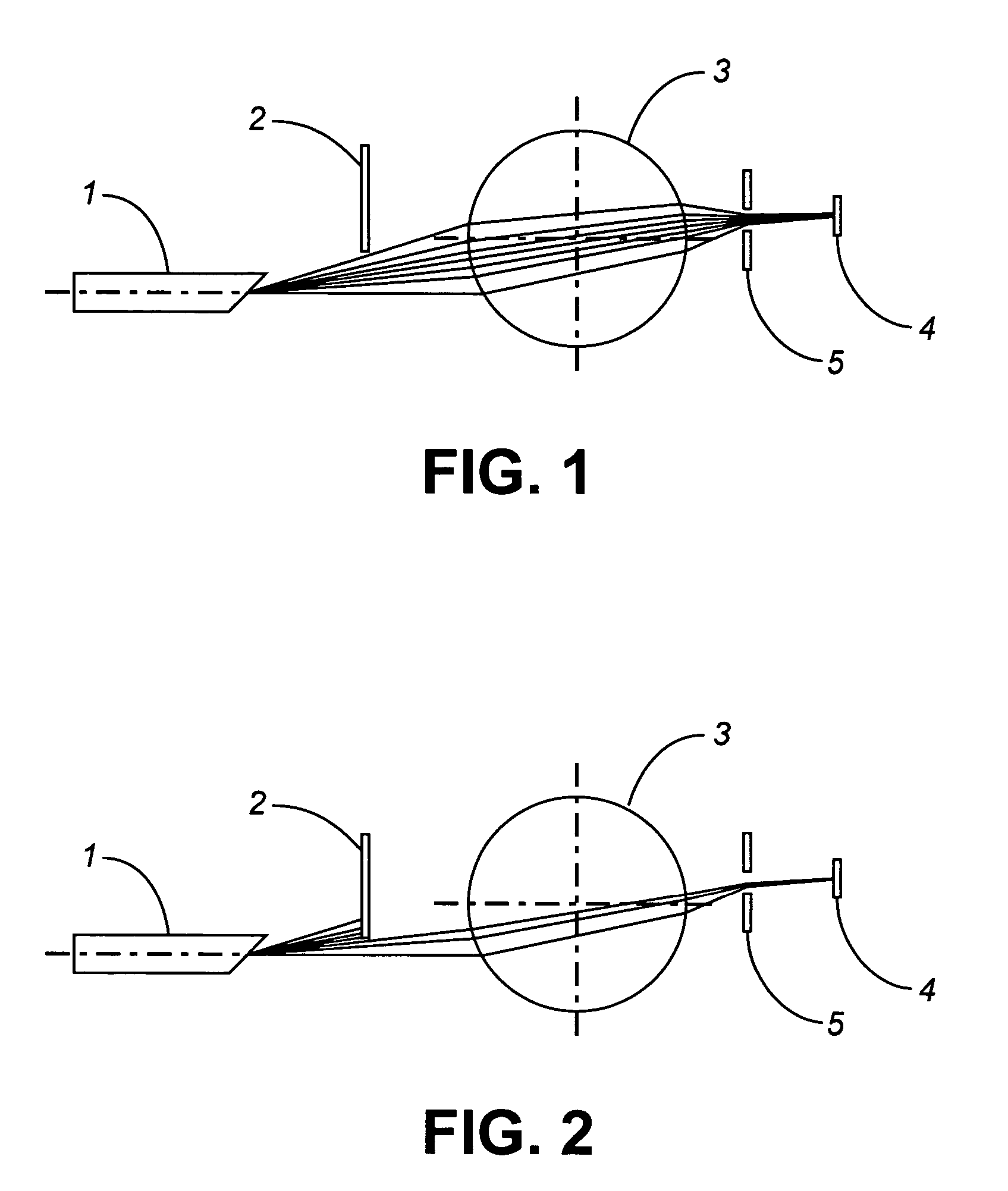
[0045]As illustrated in FIG. 1, the optical assembly according to the subject invention generally includes an optical subassembly with a single lens for coupling light transmitted from an input fiber to photosensitive area 4 of a photodetector (PD) and an integral optical blocker 2 for selectively attenuating the light (i.e. signal) when desired. In a particularly advantageous embodiment, the optical subassembly also, optionally, includes an aperture 5 located between lens 3 and photosensitive area 4 of the PD.

[0046]FIG. 1 illustrates a High Dynamic Range Receiver (HDRR), according to the subject invention, when blocking mechanism (optical attenuator) 2 is not activated and the receiver has maximum sensitivity. FIG. 2 illustrates the same embodiment as FIG. 1 but shows blocking mechanism 2 inserted into the input beam and thus attenuation of the input signal. In this embodiment, in order to reduce the amount of light reflected back from the fiber edge, the fiber edge is machined at ...


PUM


Abstract

An optical coupling assembly having an optical receiver that exhibits extended dynamic range, and, more particularly, an optical receiver that is integrated with a Variable Optical Attenuator (VOA) to extend the dynamic range of the receiver.

Description

[0001]This application is a divisional of U.S. patent application Ser. No. 10 / 342,410, entitled “Optical Receiver with High Dynamic Range”, filed on Jan. 13, 2003, now U.S. Pat. No. 6,954,580, which claims the benefit of U.S. Provisional Patent Application No. 60 / 360,937, filed Mar. 1, 2002, which are incorporated herein by reference for all purposes.FIELD OF THE INVENTION[0002]The present invention relates to an optical receiver that exhibits extended dynamic range, and more particularly to an optical coupling assembly, which ensures that the light coupled to the PD impinges at an angle of incidence selected from a range of angles. The present invention further relates to a micro-optical coupling subassembly useful to couple light to a small surface area photodetector.BACKGROUND OF THE INVENTION[0003]Reconfigurable networks that employ active switching, add-drop multiplexing, and wavelength routing cause power level variations. Power levels may also vary as a result of component de...

Claims


Application Information

Patent Timeline
Patent Type & Authority Patents(United States)
IPC IPC(8): G02B6/30G02B6/00G02B6/26G02B6/36G02B6/38G02B6/42H01L29/732
CPCG02B6/4206G02B6/266
Inventor SOSKIND, YAKOV G.ITZLER, MARKMERRITT, SCOTT
Owner LUMENTUM OPERATIONS LLC
Learn More