
Paperboard tube structures with one or more cut-and-folded plies

a technology of paperboard tubes and ply tubes, which is applied in the field of paperboard tube structures, can solve the problems of increasing the cost of paperboard tubes and the relative and achieves the effects of increasing the moment of inertia of the cross section of paperboard tubes, increasing the effective thickness of the wall, and reducing the cost of stronger plies

Inactive Publication Date: 2005-09-06
SONOCO DEV INC
View PDF10 Cites 5 Cited by
  • Summary
  • Abstract
  • Description
  • Claims
  • Application Information

AI Technical Summary

Benefits of technology

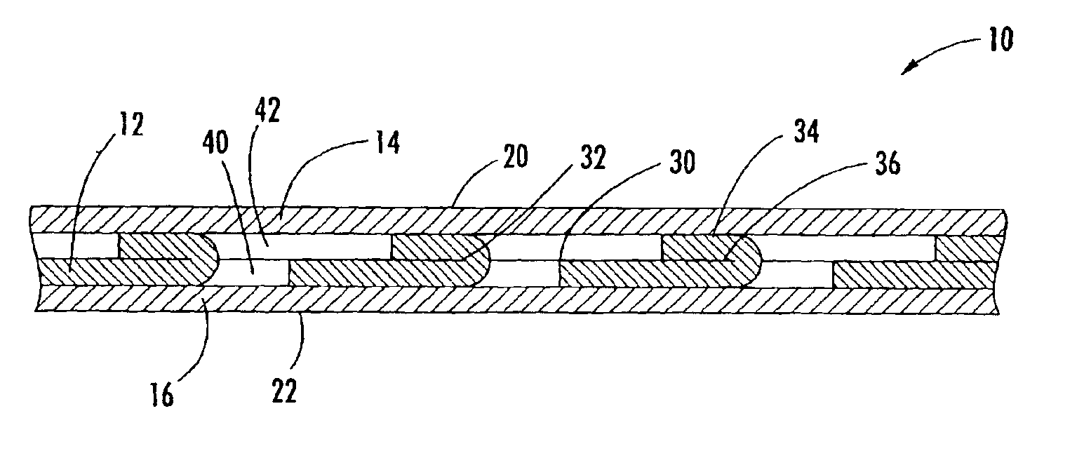
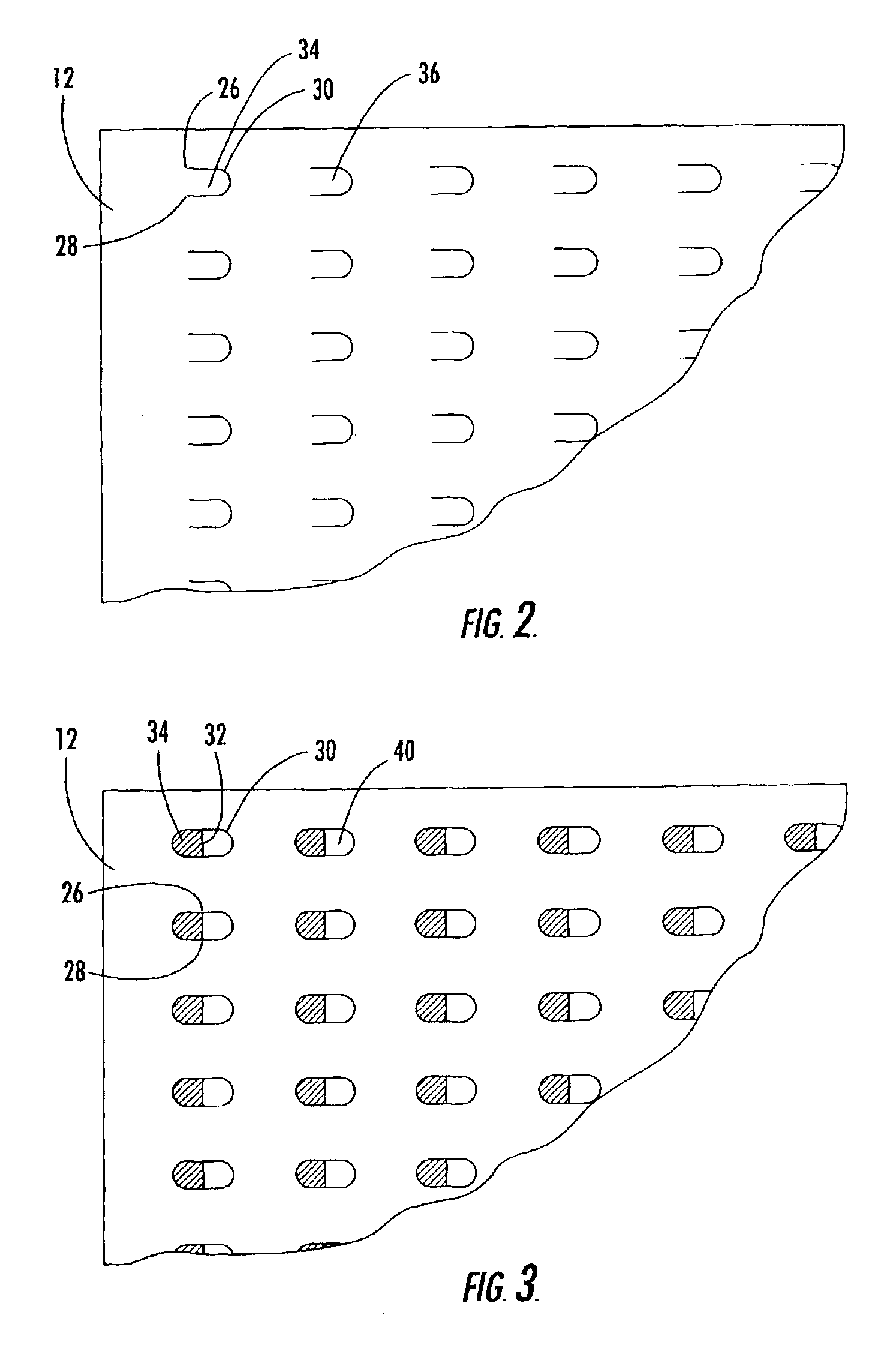
The invention is a paperboard tube made by wrapping paperboard plies around an axis. The plies include an interior ply, an exterior ply, and at least one intermediate ply with tabs. The tabs are created by nonlinear incision in the intermediate ply and are folded or rotated about a folding axis. The tabs increase the effective thickness of the wall of the paperboard tube and maintain bending stiffness while using less paperboard ply material or increasing it. The nonlinear incision can be of any geometric shape and the tabs can have adhesive on their contacting face. The paperboard tube can also have at least one partitioning ply without tabs or at least one intermediate ply with tabs folded onto its interior and exterior surfaces. The method of manufacturing the paperboard tube involves piercing the intermediate ply to form nonlinear incisions, folding or rotating the tabs about their respective folding axes, and winding the plies about an axis to form the paperboard tube structure.

Problems solved by technology

In either case, an additional amount of raw material is required, which increases the cost of the paperboard tube.
Tube strength can also be increased by using denser, stronger plies, but such stronger plies are relatively more costly.

Method used


Image

  • Paperboard tube structures with one or more cut-and-folded plies
  • Paperboard tube structures with one or more cut-and-folded plies
  • Paperboard tube structures with one or more cut-and-folded plies

Examples


Embodiment Construction

[0019]The present invention now will be described more fully hereinafter with reference to the accompanying drawings, in which some, but not all embodiments of the invention are shown. Indeed, the invention may be embodied in many different forms and should not be construed as limited to the embodiments set forth herein; rather, these embodiments are provided so that this disclosure will satisfy applicable legal requirements. Like numbers refer to like elements throughout.

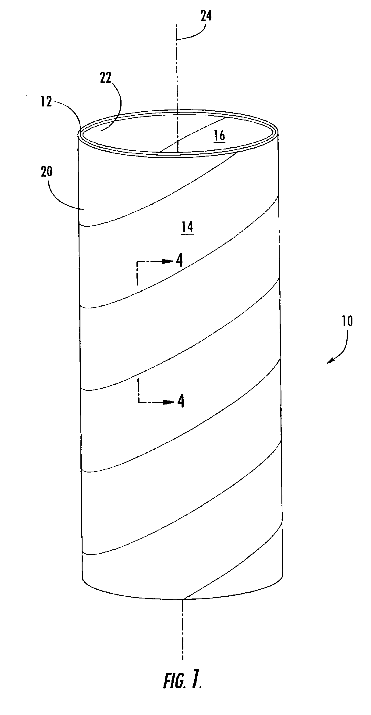
[0020]FIG. 1 illustrates a paperboard tube structure 10 of the present invention. The paperboard tube 10 of FIG. 1 is a spiral wound tube having a central axis 24 and having an inner surface 22 closest to the axis and an outer surface 20 farthest from the axis. Multiple plies are spirally wrapped about the axis and adhered together to form the paperboard tube 10 in a continuous process forming a tubular structure that is cut to form individual tube structures of desired length. In the paperboard tube 10 of FIG. 1, ...


PUM

PropertyMeasurementUnit
angleaaaaaaaaaa
thicknessaaaaaaaaaa
bending stiffnessaaaaaaaaaa

Abstract

There is provided a paperboard tube structure with an intermediate ply having cut-and-folded tabs to increase the effective thickness of the intermediate ply. The paperboard tube includes a plurality of paperboard plies wrapped one atop another about an axis with the intermediate ply positioned between an interior paperboard ply and an exterior paperboard ply. A plurality of cut-and-folded tabs are each created by a nonlinear incision in the intermediate ply that extends from a first endpoint to a second endpoint thereby creating a folding axis along a line from the first endpoint to the second endpoint. The tab is folded about the folding axis to overlie a region of the intermediate ply adjacent the folding axis. The tabs increase the effective thickness of the wall of the paperboard tube. Therefore, the bending stiffness of the paperboard tube is increased compared to a tube without cut-and-folded tabs or the tube requires less paperboard ply material to maintain an approximately equal bending stiffness as a tube without cut-and-folded tabs.

Description

FIELD OF THE INVENTION[0001]The present invention relates generally to paperboard tube structures. More particularly, the invention relates to paperboard tube structures having a construction promoting an enhanced wall thickness and bending stiffness for a given mass of the tube structure.BACKGROUND OF THE INVENTION[0002]Within the paperboard tube industry, it is desirable to minimize the amount of ply material used to manufacture a paperboard tube. Paperboard tube structures are often used in consumer good applications such as paper towel rolls or toilet paper rolls, but they are also used in manufacturing applications such as cores for supporting rolled sheet material or in industrial applications such as forms or templates for columnar structures.[0003]Tube structures must possess structural properties commensurate with their intended applications. Paperboard tube designs and manufacturing procedures preferably should minimize the amount of raw materials needed to achieve the req...

Claims


Application Information

Patent Timeline
Patent Type & Authority Patents(United States)
IPC IPC(8): B31C3/00B65D3/22B65D3/00
CPCB31C3/00B65D3/22Y10T156/1015Y10T156/1062Y10T428/24331Y10T156/1051Y10T156/1064Y10T428/1303Y10T156/1026
Inventor VAN DE CAMP, WIMNIU, XIAOKAI
Owner SONOCO DEV INC
Learn More