
Pulse modulator for nonradiative dielectric waveguide, and millimeter wave transmitter/receiver using the same

Inactive Publication Date: 2006-06-27
KYOCERA CORP
View PDF13 Cites 4 Cited by
  • Summary
  • Abstract
  • Description
  • Claims
  • Application Information

AI Technical Summary

Benefits of technology

[0014]The invention has been devised in view of the above situation, and an object of the invention is to provide a pulse modulator wherein improvements are made to increase the fabrication reproducibility of the pulse modulator and facilitate impedance matching for operation at the desired frequency so that the characteristics of the pulse modulator can be obtained stably and with good reproducibility, thereby achieving a pulse modulator easy to manufacture and suitable for mass production.
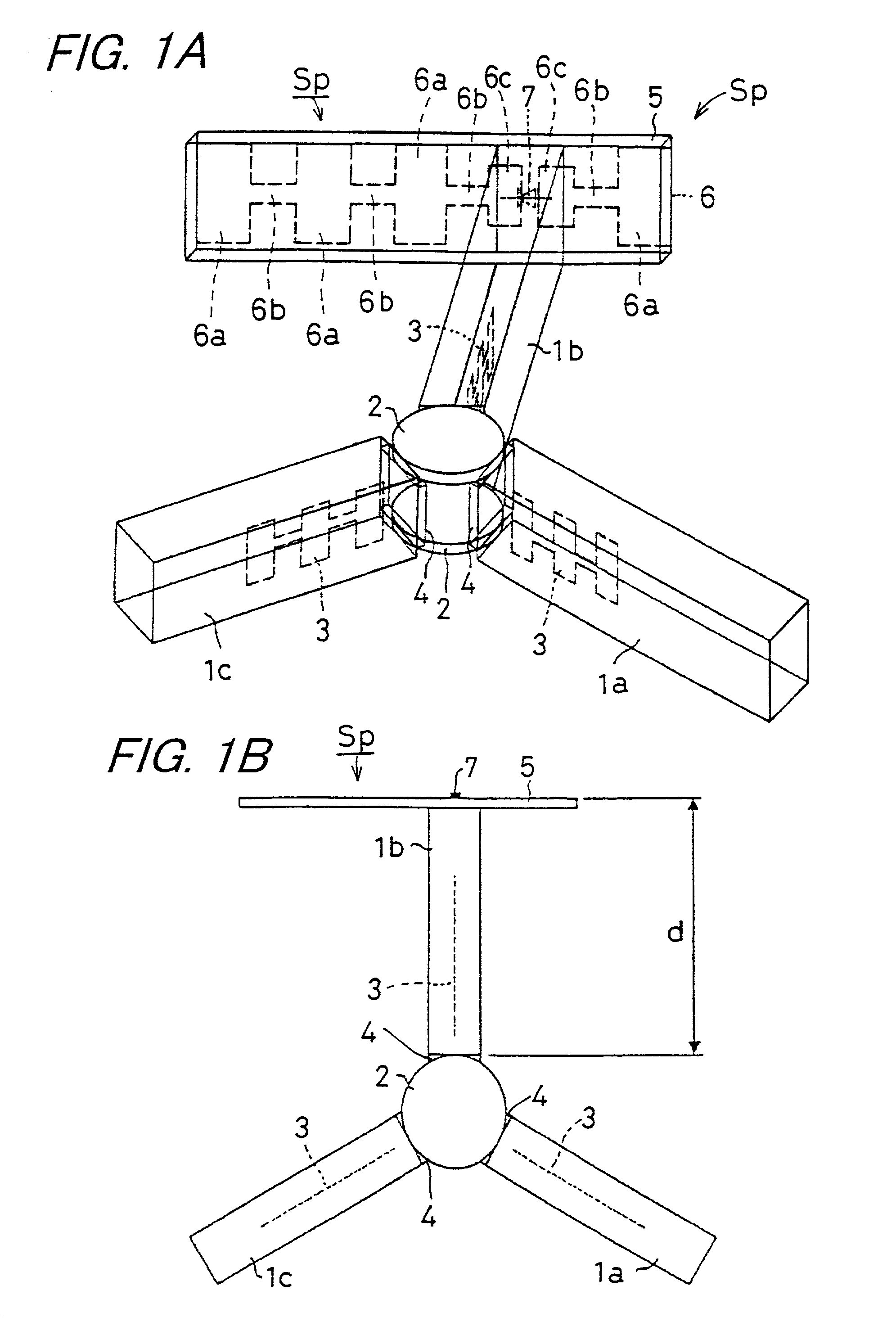
[0016]According to the invention, since the impedance matching for enabling operation at the desired frequency is achieved by controlling the distance from the ferrite plates to the Schottky barrier diode, the need for the gap or the dielectric sheet required in the prior art is eliminated, thus reducing the number of components used and enhancing fabrication reproducibility. Further, since the impedance matching for enabling operation at the desired frequency can be easily achieved, the characteristics of the pulse modulator can be obtained stably and with good reproducibility. The pulse modulator of the invention is therefore easy to manufacture and has high reliability.
[0017]Furthermore, since there is no need to provide a gap between the mode suppressor and the Schottky barrier diode as in the prior art, component positioning is greatly simplified, and the pulse modulator can be produced stably and with good reproducibility, thereby the mass producibility is greatly improved.
[0019]According to the invention, there is offered the effect of providing greater freedom in controlling the distance from the ferrite plates to the Schottky barrier diode, and making it possible to readily adapt to operations at various desired frequencies.
[0047]According to the invention, isolation characteristics for pulse modulation such as ASK modulation applied to the millimeter wave are improved, and as a result, when the invention is applied to a millimeter wave radar or the like, the detection range of the radar can be extended.
[0071]According to the invention, isolation characteristics for pulse modulation such as ASK modulation applied to the millimeter wave signal are improved, and the millimeter wave signal for transmission is prevented from being introduced into the mixer via the circulator; therefore, when the invention is applied to a millimeter wave radar module, noise in the received signal reduces and the detection range increases, so that the detection range of the millimeter radar can be further extended.

Problems solved by technology

That is, the manufacturing accuracy and the positioning accuracy of these components have been difficult to manage, and this, coupled with poor fabrication reproducibility, has lead to low manufacturing efficiency; hence, the prior art has had the problem that it cannot ensure high reliability, nor is it suitable for mass production.
If such a pulse modulator is used for a millimeter wave transmitter / receiver, since ASK modulation is insufficient, there occurs the problem that millimeter wave isolation characteristics degrade and, when it is applied to a millimeter wave radar or the like, accurate detection becomes difficult.

Method used


Image

  • Pulse modulator for nonradiative dielectric waveguide, and millimeter wave transmitter/receiver using the same
  • Pulse modulator for nonradiative dielectric waveguide, and millimeter wave transmitter/receiver using the same
  • Pulse modulator for nonradiative dielectric waveguide, and millimeter wave transmitter/receiver using the same

Examples


working example

[0121

[0122]The pulse modulator of FIG. 1 was constructed as described below. Two Al plates, each with a thickness of 6 mm, were arranged as parallel plate conductors, one separated from the other by a distance of 1.8 mm. Three mode suppressors 1a to 1c, each having a rectangular cross section of 1.8 mm (height)×0.8 mm (width) and made of glass ceramics having a dielectric constant of 4.8, were connected to two ferrite disks 2, and were placed between the parallel plate conductors, the mode suppressors being arranged extending radially and spaced 120 degrees apart from each other. The mode suppressors 1a to 1c each contain a strip line conductor 3 made of Cu foil formed in a λ / 4 choke pattern.

[0123]At this time, the upper and lower surfaces of each of the mode suppressors 1a to 1c were made flush with the principal surfaces of the two ferrite disks 2. More specifically, the two ferrite disks 2 were arranged opposite each other on the inner surfaces of the respective parallel plate co...


PUM


Abstract

A pulse modulator includes a circulator which comprises: two ferrite plates; a plurality of mode suppressors for transmitting therethrough an LSM mode electromagnetic wave while shutting off an LSE mode electromagnetic wave; and an impedance matching member mounted on one end face of each of the mode suppressors, wherein a pulse modulation switch having a Schottky barrier diode is mounted on the other end face of any one of the mode suppressors in such a manner that the direction of application of a bias voltage to the Schottky barrier diode coincides with the direction of electric field of the LSM mode electromagnetic wave, and wherein the distance from an edge of the ferrite plates to the Schottky barrier diode is set approximately equal to nλ / 2. Herein, n is an integer not smaller than 1, and λ is the wavelength of the high frequency signal.

Description

BACKGROUND OF THE INVENTION[0001]1. Field of the Invention[0002]The present invention relates to a pulse modulator, incorporated in a millimeter wave integrated circuit, a millimeter wave radar module of nonradiative dielectric waveguide type, or the like, for modulating a millimeter wave signal by ASK (Amplitude Shift Keying) or like modulation scheme, and also relates to a millimeter wave transmitter / receiver of nonradiative dielectric waveguide structure using the same.[0003]2. Description of the Related Art[0004]FIG. 8 shows the basic structure of a prior art nonradiative dielectric waveguide (hereinafter called the NRD guide) for transmitting therethrough a high frequency signal in the microwave or millimeter wave region. As shown, the structure comprises a dielectric waveguide 13 of rectangular or square cross section that is placed between parallel plate conductors 11 and 12 arranged in parallel to each other with a prescribed gap “a” provided therebetween. If this gap “a” sa...

Claims


Application Information

Patent Timeline
IPC IPC(8): H04B1/26H04M1/00H01P1/38H01P1/16H01P1/383H01P3/16
CPCH01P1/383
Inventor KII, HIRONORIHIRAMATSU, NOBUKI
Owner KYOCERA CORP
Learn More