
Slot line based high frequency oscillator using two-port element

a high frequency oscillator and slot line technology, applied in the field can solve the problems of high frequency oscillators, and achieve the effects of convenient circuit design, high production efficiency, and convenient increase of oscillation outpu

Inactive Publication Date: 2006-06-13
NIHON DEMPA KOGYO CO LTD +1
View PDF2 Cites 12 Cited by
  • Summary
  • Abstract
  • Description
  • Claims
  • Application Information

AI Technical Summary

Benefits of technology

[0009]It is an object of the present invention to provide a highly productive high frequency oscillator which facilitates a variety of circuit designs including the impedance matching and readily provides an increased oscillation output.
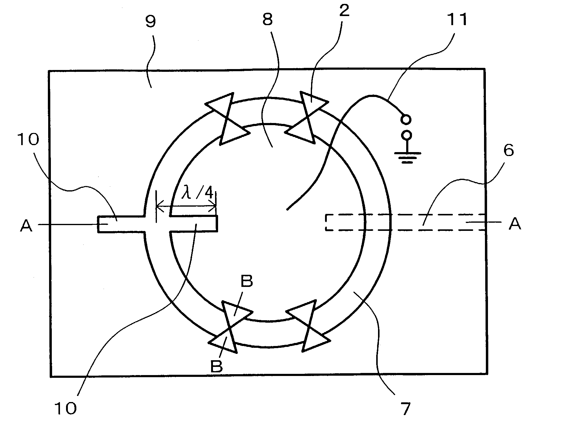
[0012]In the present invention, since the slot line resonator circuit is applied for connection of the two-port negative resistance element, the negative resistance element can be grounded in high frequency terms on the one principal surface of the substrate. This eliminates the need for a via hole otherwise required when a microstrip line resonator circuit is used, so that the negative resistance element is readily mounted with a reduced circuit loss and parasitic reactance component, resulting in the oscillation characteristic advantageous in the microwave band and millimeter band. Also, since the slot line resonator circuit has different impedances at different points on the slot line due to a standing wave generated along the slot line, the impedance matching can be readily achieved between the negative resistance element and slot line resonator circuit only by appropriately determining where the negative resistance element should be connected, without providing a matching line or a matching circuit. The ease of impedance matching results in readiness in the designing of various circuits including the impedance matching, readiness in increasing the output of the oscillator, and a higher productivity of the oscillator.
[0014]As described above, the present invention can facilitate the configuration of the high frequency oscillator, increase the oscillation output, oscillate at higher frequencies, and improve the quality of the oscillation through the utilization of the transmission characteristic and line structure of the slot line routed on one principal surface of the substrate and the output line electrically connected to the slot line. Specifically, the high frequency oscillator configured according to the present invention can provide the following advantages.
[0015](1) The use of a slot line permits a semiconductor diode or a negative resistive IC (integrated circuit) chip, which serves as the negative resistance element, to be mounted on the one principal surface of the substrate by surface mounting or flip-chip mounting based on bump techniques, so that the negative resistance element can be satisfactorily grounded in high frequency terms. The resulting high frequency oscillator also excels in the oscillation at higher frequencies, for which a high mounting accuracy is required, as well as in the productivity. Particularly, a reduction in cost can be readily accomplished for a high frequency oscillator for use in a millimeter band and the like by using relatively inexpensive semiconductor diodes.

Problems solved by technology

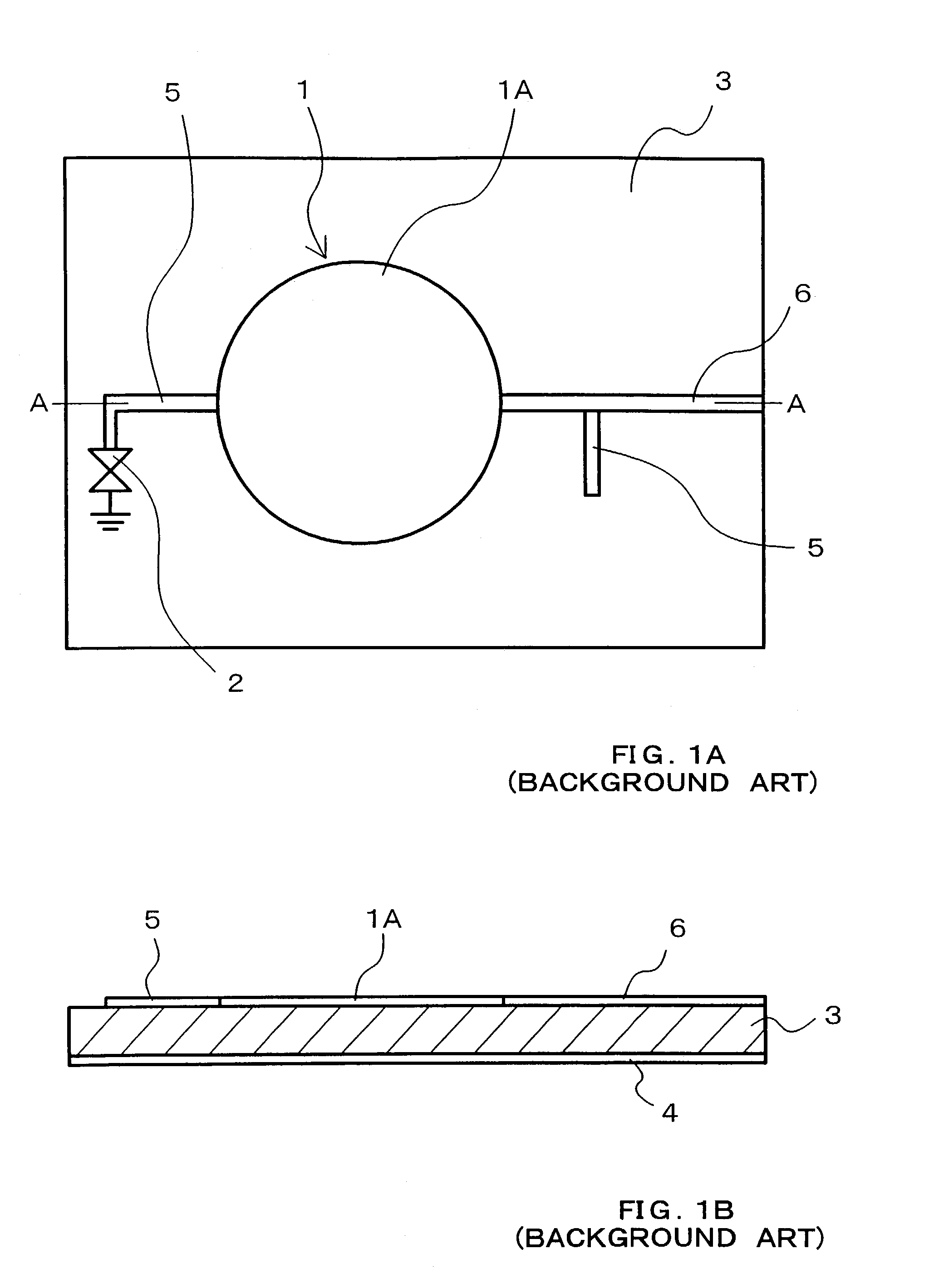
The inventors found that the problem in the conventional high frequency oscillator was caused by the microstrip line resonator circuit which had the circuit conductor (i.e., signal line) formed on one principal surface of the substrate and the ground conductor on the other principal surface.

Method used


Image

  • Slot line based high frequency oscillator using two-port element
  • Slot line based high frequency oscillator using two-port element
  • Slot line based high frequency oscillator using two-port element

Examples


first embodiment

[0050]A high frequency oscillator according to the present invention comprises a ground conductor formed substantially over the entirety of one principal surface of substrate 3 made, for example, of a dielectric material. This ground conductor is formed with a loop-shaped elongated opening which constitutes loop-shaped or endless slot line resonator circuit 7. In the ground conductor, a portion located inside the loop-shaped opening of slot line resonator circuit 7 is called “inner conductor 8” while a portion located outside the opening is called “outer conductor 9.” In the illustrated high frequency oscillator, slot line resonator circuit 7 comprises an annular slot line. A high frequency component propagates through the slot line by the action of an electric field and a magnetic field produced between inner conductor 8 and outer conductor 9.

[0051]Slot line resonator circuit 7 has an electric length set at an integer multiple of λ, where λ represents a wavelength corresponding to ...

second embodiment

[0070]A high frequency oscillator illustrated in FIGS. 7A to 7C is a variable frequency version of the high frequency oscillator according to the Here, microstrip line stub 15 disposed on the other principal surface of substrate 3 is divided at the midpoint thereof, and varactor diode 13 is inserted at this dividing position such that the anode and cathode of varactor diode 13 are connected to the divided halves of microstrip line stub 15, respectively. Though not shown herein, a control voltage is applied between the cathode and anode of varactor diode 13.

[0071]In the high frequency oscillator thus configured, varactor diode 13 is inserted in series with slot line resonator circuit 7, so that the capacitance of varactor diode 13 changes in response to the control voltage applied between the anode and cathode of varactor diode 13, as mentioned above, causing an associated change in the electric length of slot line resonator circuit 7 to vary the oscillation frequency.

[0072]A high f...

fourth embodiment

[0076]As described above, the variable frequency high frequency oscillator can be provided in simple configurations when one end of slot line resonator circuit 7 is formed either with an electrically open end or with a short-circuited end. While the control voltage is applied to the cathodes of varactor diodes 13 through lead wire 17, the control voltage may be applied from the other principal surface of substrate 3 through a via hole formed through substrate 3.


PUM

PropertyMeasurementUnit
Massaaaaaaaaaa
Lengthaaaaaaaaaa
Frequencyaaaaaaaaaa

Abstract

A high frequency oscillator has a substrate, a resonator circuit which is disposed on one principal surface of the substrate and consists of a closed loop-shaped slot line including an inner conductor and an outer conductor, an electric boundary point set on the slot line, a two-port negative resistance element for connecting between the inner conductor and outer conductor, and an output line electrically connected to the slot line. The electric boundary point is set by connecting, for example, a stub to the resonator circuit. The stub functions as an electrically short-circuited end or an electrically open end. A Gunn diode is preferably used for the negative resistance element, and inserted at a position of the slot line resonator circuit at which impedance matching is achieved.

Description

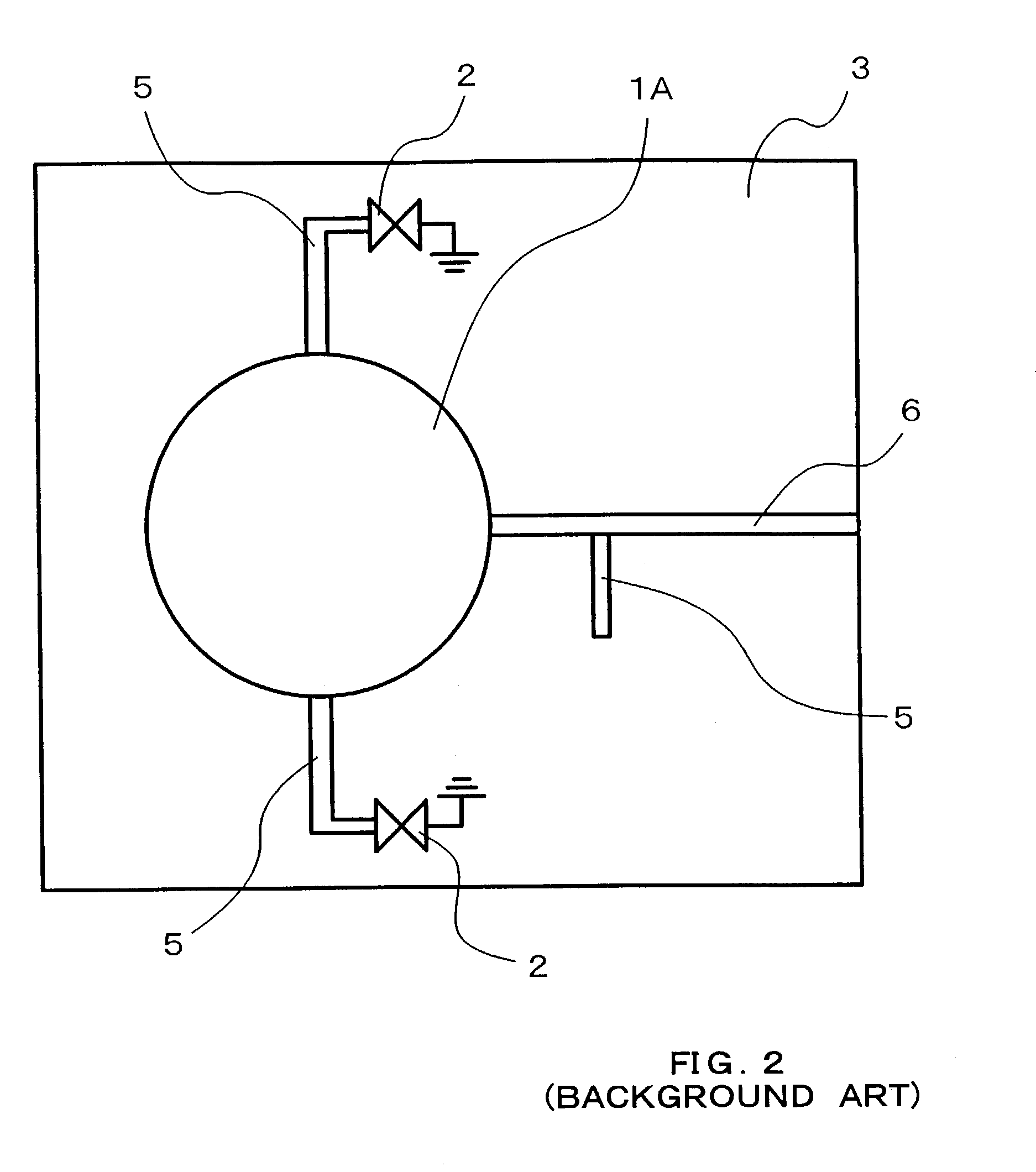
BACKGROUND OF THE INVENTION[0001]1. Field of the Invention[0002]The present invention relates to a high frequency oscillator for a microwave band and a millimeter band which employs a two-port element as an oscillation element, and more particularly, to a high frequency oscillator which employs a slot line based planar resonator circuit.[0003]2. Description of the Related Arts[0004]A high frequency oscillator for a microwave band or a millimeter band is a highly significant component in terms of performance as well as cost even among main components used in a high frequency apparatus or a high speed apparatus. A high frequency oscillator of the type mentioned above employs a planar resonator circuit of a microstrip line type. FIG. 1A is a plan view illustrating an example of such a conventional high frequency oscillator, and FIG. 1B is a cross-sectional view taken along a line A—A in FIG. 1A.[0005]The high frequency oscillator illustrated in FIGS. 1A and 1B comprises microstrip line...

Claims


Application Information

Patent Timeline
IPC IPC(8): H03B5/18H03B9/14
CPCH03B5/1847
Inventor AIKAWA, MASAYOSHITANAKA, TAKAYUKIASAMURA, FUMIOOITA, TAKEO
Owner NIHON DEMPA KOGYO CO LTD
Learn More