Semiconductor device and method of manufacturing the same
- Summary
- Abstract
- Description
- Claims
- Application Information
AI Technical Summary
Benefits of technology
Problems solved by technology
Method used
Image
Examples
first embodiment
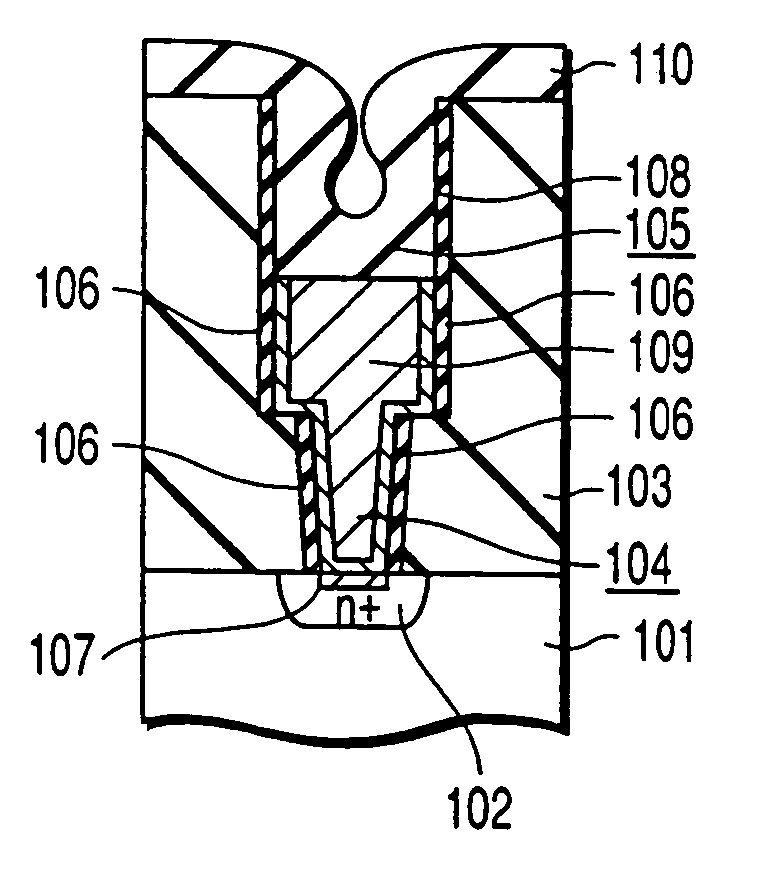
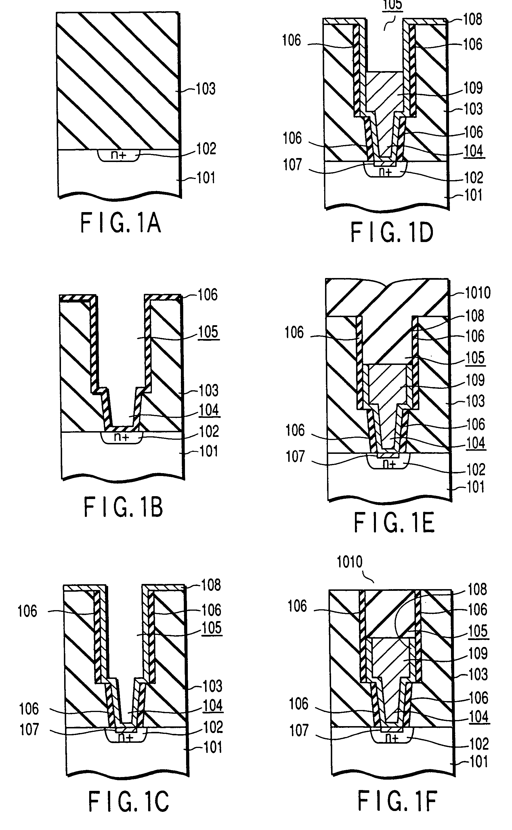
[0105]FIGS. 1A to 1F are cross sectional views collectively showing a method of manufacturing a semiconductor device according to a first embodiment of the present invention. These drawings show cross sections in a direction perpendicular to the longitudinal direction of the channel of a MOS transistor of a DRAM cell.
[0106]In the first step, an n-type drain diffusion layer 102, etc. are formed by a known method in a silicon substrate 101 to finish forming a MOS transistor, followed by forming an interlayer insulating film (SiO2 film) 103 on the entire surface, as shown in FIG. 1A. Then, a contact hole 104 exposing the n-type drain diffusion layer 102 and a wiring trench 105 connected to the n-type drain diffusion layer 102 via the contact hole 104 are formed in the interlayer insulating film 103, followed by forming a silicon nitride film 106 over the entire surface, as shown in FIG. 1B. The silicon nitride film 106 thus formed is selectively removed by RIE (reactive ion etching) su...
second embodiment
[0133]The first embodiment is directed to formation of a silicon nitride film having a high chlorine concentration. On the other hand, the second embodiment is directed to formation of a silicon nitride film having a high chlorine concentration and containing an excess silicon. FIGS. 1A to 1F will also be used for describing the second embodiment.
[0134]The second embodiment is equal to the first embodiment up to the step shown in FIG. 1D. Then, a silicon nitride film (HCD-SiN film) 10 is formed on the entire surface in a manner to fill the inner space of the wiring trench 6 by an LPCVD method using a mixed gas consisting of Si2Cl6 and NH3, as shown in FIG. 1E. The silicon nitride film 10 is formed at a temperature of 600° C., a reactor inner pressure of 0.5 Torr, and a NH3 / Si2Cl6 flow rate ratio of 2000 sccm / 20 sccm. The film-forming rate is 1.4 nm / min.
[0135]In the next step, the excess HCD-SiN film 10 outside the wiring trench 6 is removed by CMP under the conditions equal to those...
third embodiment
[0146]With progress in miniaturization of the device element, it is necessary to decrease the resistance of the gate electrode. Therefore, it is necessary in the next era to change the polymetal gate structure employed nowadays into a metal gate electrode. On the other hand, since it is difficult to achieve fine processing of a metal film by etching, a damascene gate process (A. Yagishita, et al., IEDM Tech. Digest, 1998: p. 785) is employed for forming a metal gate electrode. Also, a dummy gate is required for forming a trench in which the metal gate electrode is buried. A method of manufacturing a MOS transistor by using a metal gate electrode according to a third embodiment of the present invention will now be described with reference to FIGS. 11A to 11I.
[0147]In the first step, a shallow trench is formed in a surface region of a silicon substrate 121, followed by forming a thermal oxide film 122 on the entire surface and subsequently burying a device element separating insulatin...
PUM
 Abstract
Description
Claims
Application Information
 - R&D
- Intellectual Property
- Life Sciences
- Materials
- Tech Scout
- Unparalleled Data Quality
- Higher Quality Content
- 60% Fewer Hallucinations
Browse by: Latest US Patents, China's latest patents, Technical Efficacy Thesaurus, Application Domain, Technology Topic, Popular Technical Reports.
© 2025 PatSnap. All rights reserved.Legal|Privacy policy|Modern Slavery Act Transparency Statement|Sitemap|About US| Contact US: help@patsnap.com


